TwinCAT project setup
Import the EtherCAT Subdevice Information (ESI) file of the FoE example.
Copy the ESI filename
ECAT-FOE.xml, generated by the SSC tool, from the SSC project folder to the<TwinCAT_installation_folder>/<Version>/Config/io/EtherCAT/folder.Create a new project.
Select File > New > Project.
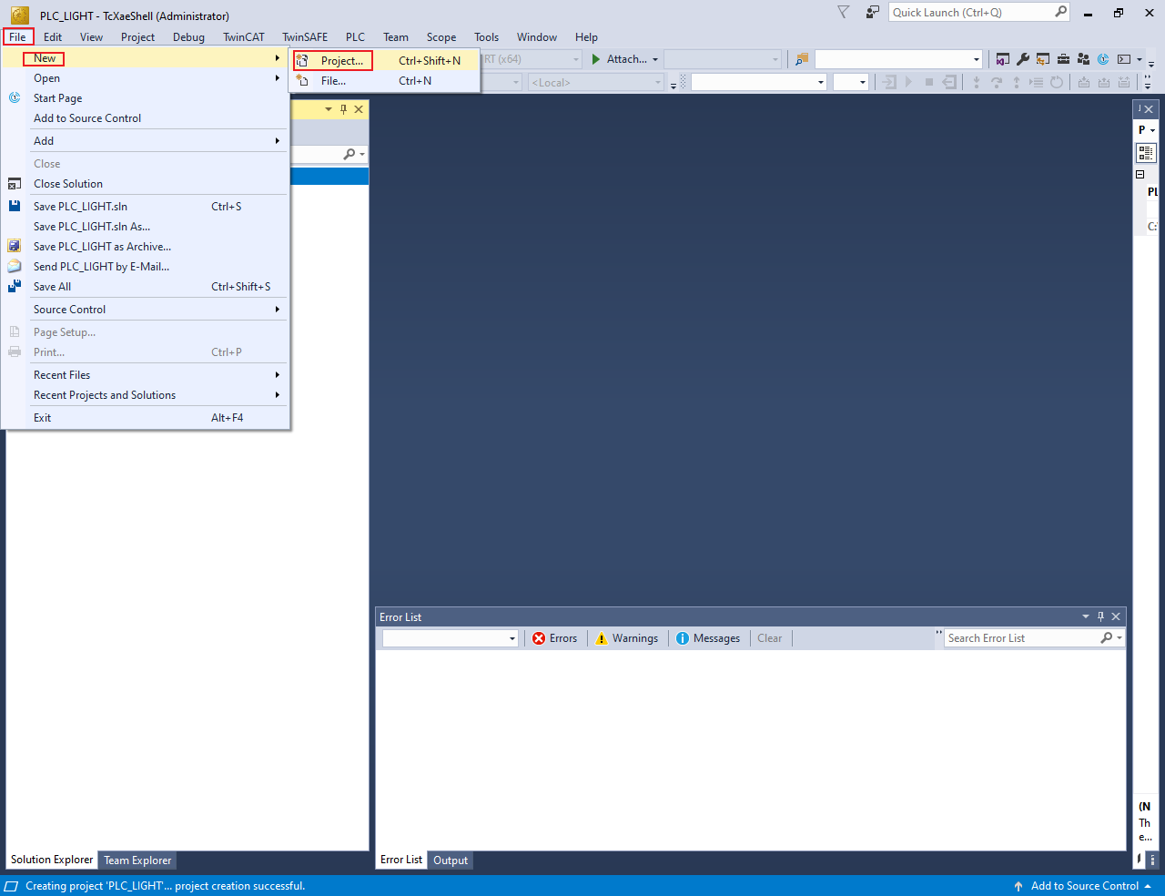
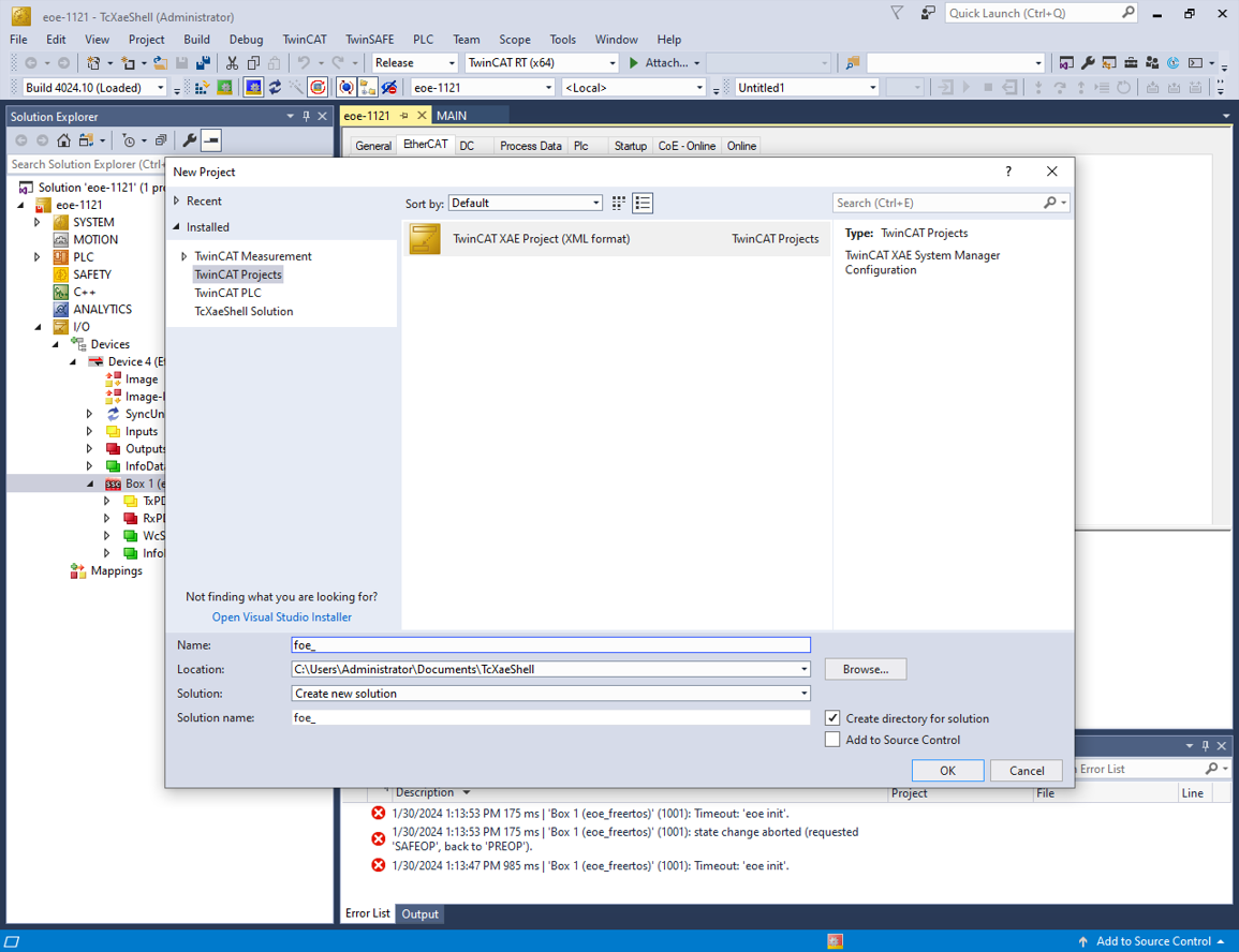
The New Project dialog box appears.
Select TwinCAT Projects.
Click OK.
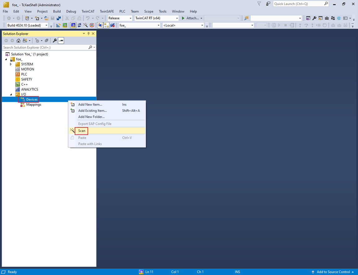
Scan for the subdevices.
In the Solution Explorer view, expand I/O.
Right-click on Device and select Scan.
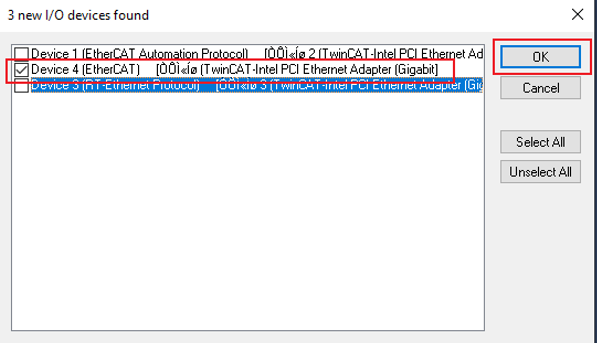
The scanned devices appear in theI/O devices found dialog box.
Select the network interface connected with the MIMXRT1180-EVK board.
Click OK.
Update the ESI file to E2PROM.
Note: The E2PROM must be updated if the FoE example is set up first time on the MIMXRT1180- EVK.
Under Device, double-click Box1. The TwinCAT Project dialog box appears.
Click the EtherCAT tab.
Click the Advanced Settings button.

The Advanced Settings dialog box appears.
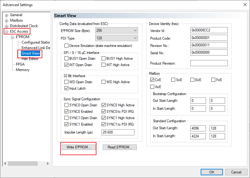
From the left pane of the Advanced Settings dialog box, select ESC Access > Smart View.
Click the Write E2PROM button.
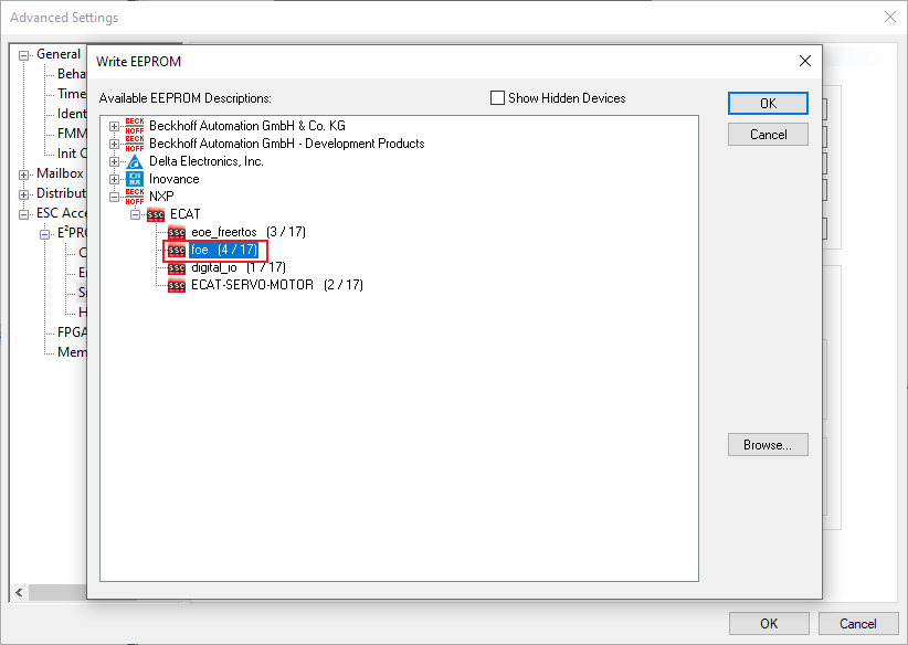
From the available EEPROM list, select NXP > ECAT > foe.
Click OK.
Remove the device and rescan the device.
Configure the subdevice.
Click the DC tab.
From the Operation Mode field, select the SM-Synchron or DC-Synchron option.

Program the PLC code.
In the Solution Explorer view, right-click on PLC.
Select Add New Item.
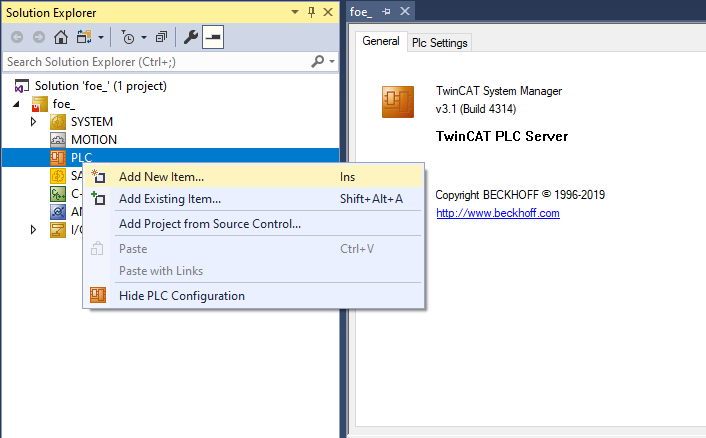
The Add New Item dialog box appears.
From the Installed list in the left pane, select PLC Templates.
Select Standard PLC Project.
Click OK.

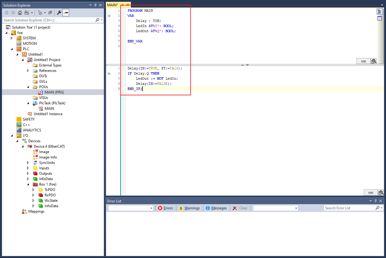
To open the PLC edit page, select MAIN (PRG) under PLC.
Copy the code below and paste it in the MAIN view.
PROGRAM MAIN
VAR
Delay : TON;
LedIn AT %I* : BOOL;
LedOut AT %Q* : BOOL;
END_VAR
Delay(IN := TRUE, PT := T#1S);
IF Delay.Q THEN
LedOut := NOT LedIn;
Delay(IN := FALSE);
END_IF;
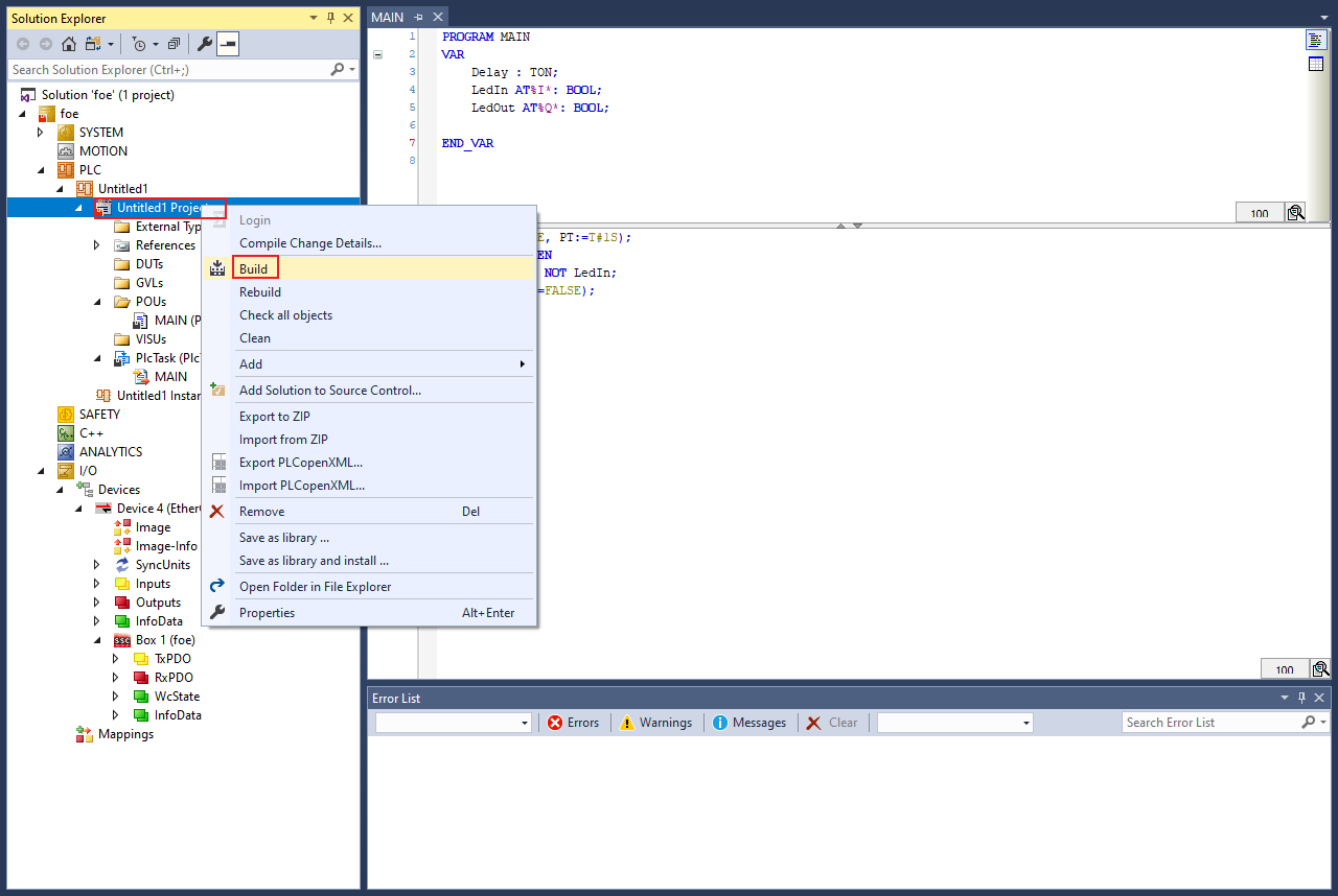
To build the PLC code, right-click on the PLC project and select Build.
Map the PLC variables to the subdevice IO channel.
Right-click on MAIN.LedIn, select Change Link.
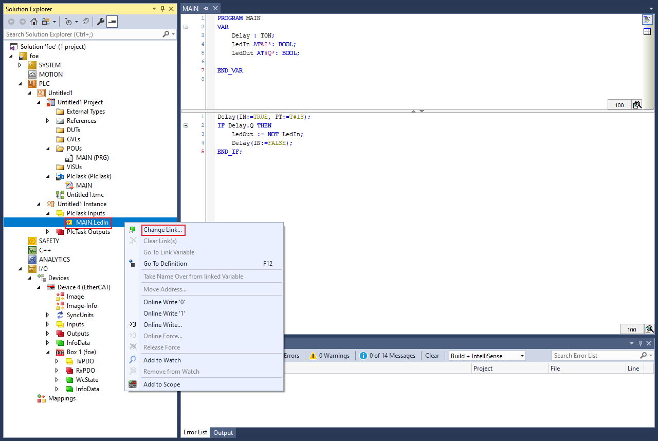
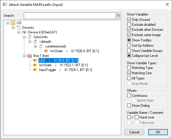
The Attach Variable MAIN.LedIn (Input) dialog box appears.
Select LED.
Click OK.
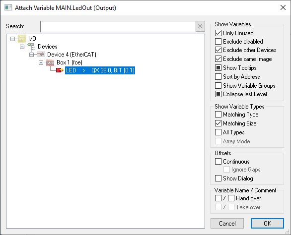
In the Solution Explorer, under PlcTask Outputs, right-click on MAIN.LedOut and select Change Link.
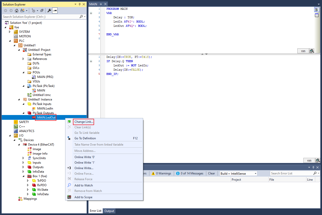
The Attach Variable MAIN.LedOut (Output) dialog box appears.
Select LED.
Click OK.
Activate Configuration
To activate the configuration, select TwinCAT > Restart TwinCAT (Config Mode).

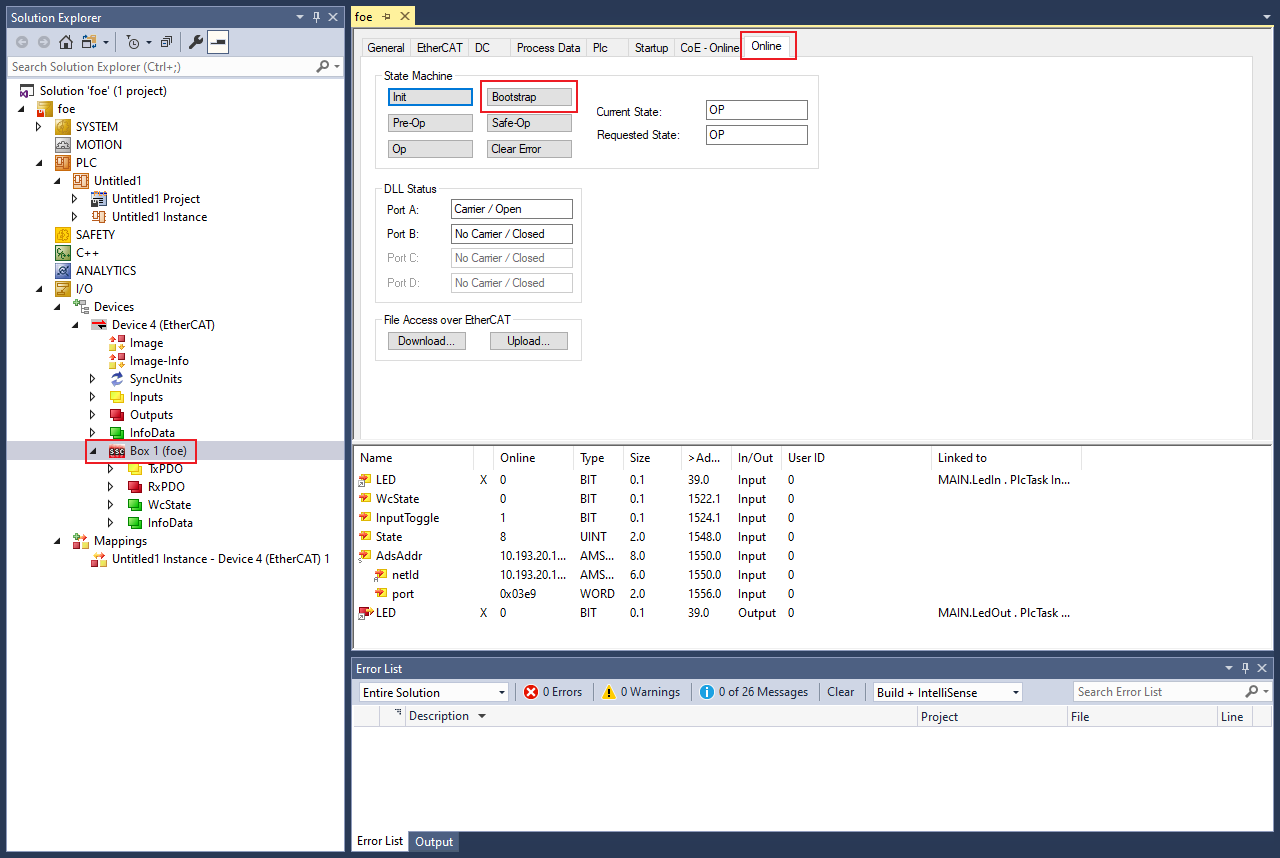
FoE image upgrade.
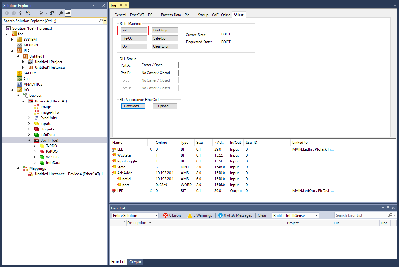
Click Device > Box1 > Online > Bootstrap.
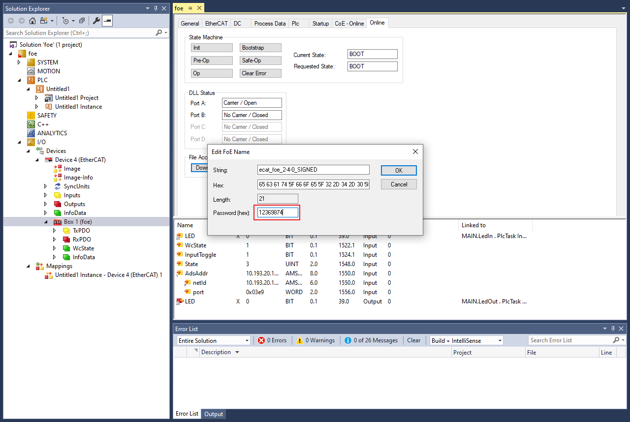
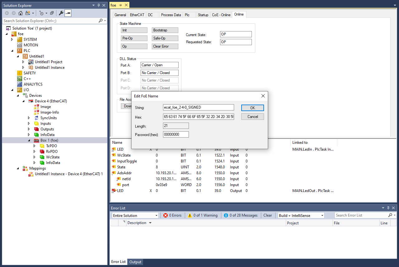
Click Download > ecat_foe_2-4-0_SIGNED.bin > Password’ > OK to upgrade the image.
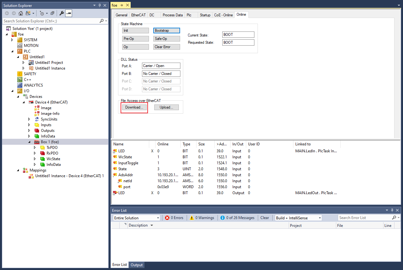
Note: FoE download Password: ‘12369874’.
The serial terminal prints the following output.
storage addr: 0x28240000
FoE_StoreImage: processed 256 bytes
FoE_StoreImage: processed 512 bytes
...
FoE_StoreImage: upload complete (42028 bytes)
write magic number offset = 0x43ff00
Update image success
After download, click ‘Init’ to restart the board.
The serial terminal prints the following output.
System reset...
hello sbl.
Bootloader Version 1.9.0
Primary image: magic=good, swap_type=0x1, copy_done=0x3, image_ok=0x1
Secondary image: magic=good, swap_type=0x1, copy_done=0x3, image_ok=0x3
Boot source: none
Swap type: test
Starting swap using move algorithm.
Bootloader chainload address offset: 0x40000
Reset_Handler address offset: 0x40400
Jumping to the image

Start the SSC FoE example...
Image version: 2.4.0
Image state: testing
Set image as confirmed: success
FoE image download.
Click Upload to choose the file to download.

To download the upgraded image, click OK.
Note: The download image name must be the same as the upgraded image name.