Wireless UART
This section describes the implemented profiles and services, user interactions, and testing methods for the Wireless UART application.
Implemented profile and services
The Wireless UART application implements both the GATT client and server for the custom Wireless UART profile and services.
Wireless UART Service (UUID: 01ff0100-ba5e-f4ee-5ca1-eb1e5e4b1ce0)
Battery Service v1.0
Device Information Service v1.1
The Wireless UART service is a custom service that implements a custom writable ASCII Char characteristic (UUID: 01ff0101-ba5e-f4ee-5ca1-eb1e5e4b1ce0) that holds the character written by the peer device.
The application behaves at first as a GAP central node. It enters GAP Limited Discovery Procedure and searches for other Wireless UART devices to connect. To change the device role to GAP peripheral, use the ROLESW button. The device enters GAP General Discoverable Mode and waits for a GAP central node to connect.
Parent topic:Wireless UART
Supported platforms
The following platforms support the Wireless UART application:
KW45B41Z-EVK
K32W148-EVK
FRDM-MCXW71
KW47-EVK
MCXW72-EVK
FRDM-MCXW72
Parent topic:Wireless UART
User interface
After flashing the board, the device is in idle mode (all LEDs flashing). To start scanning, press the SCANSW button. When in GAP Limited Discovery Procedure of GAP General Discoverable Mode, CONNLED is flashing. When the node connects to a peer device, CONNLED turns solid. To disconnect the node, hold the SCANSW button pressed for 2-3 seconds. The node then re-enters GAP Limited Discovery Procedure.
See the table below for hardware references for the Wireless UART application.
Platform |
SCANSW |
CONNLED |
ROLESW |
|---|---|---|---|
KW45B41Z-EVK / K32W148-EVK |
SW2 |
LED2 |
SW3 |
FRDM-MCXW71 |
SW2 |
Blue LED |
SW4 |
KW47-EVK / MCXW72-EVK |
SW2 |
LED2 |
SW3 |
FRDM-MCXW72 |
SW4 |
Blue LED |
SW2 |
Parent topic:Wireless UART
Usage
The application is built to work with another supported platform running the same example or with the Wireless UART from the IoT Toolbox application.
When testing with two boards, perform the following steps:
Open a serial port terminal and connect them to the two boards, in the same manner described in Testing devices. The start screen is blank after the board is reset.
The application starts as a GAP central. To switch the role to a GAP peripheral, press the role switch. Depending on the role, when pressing the SCANSW, the application starts either scanning or advertising.
As soon as the CONNLED turns solid on both devices, the user can start writing in one of the consoles. The text appears on the other terminal.
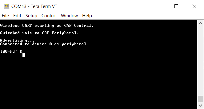
After creating a connection, the role (central or peripheral) is displayed on the console. The role switch can be pressed again before creating a new connection. See the figure below.
When testing with a single board and the IoT Toolbox, perform the following steps:
Open a serial port terminal and connect the board in the same manner described in Testing devices. The start screen is blank after the board is reset.
Press the role switch button to behave as a GAP peripheral and then press the SCANSW button to start advertising. The IoT Toolbox app can then connect. Select UART instead of Console and start typing, as shown in the Figure 1.
Parent topic:Wireless UART
Parent topic:Bluetooth LE stack and demo applications