Setting Coordinator properties
To set the channel mask and Node Power descriptor, use the below steps:
Step 1: Expand the Coordinator node in the editor. This reveals the default set of features for the Coordinator, ZDO endpoint, and ZDO servers.
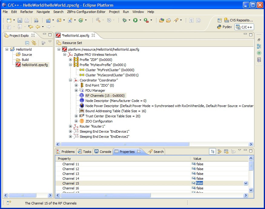
Step 2: Click on the RF Channels element to modify the channel mask.
There are 16 channels available, numbered 11 to 26, which are now shown in the Properties tab. A single channel or a set of channels can be selected for the channel mask, as required.
Step 3: In the Properties tab, set the desired channel(s) to true (by right-clicking on the value and using the drop-down box).
Channel Mask Selection
Step 4: Click to select the Node Power Descriptor.
Step 5: Edit the properties in the Properties tab, as required.
To add a new endpoint
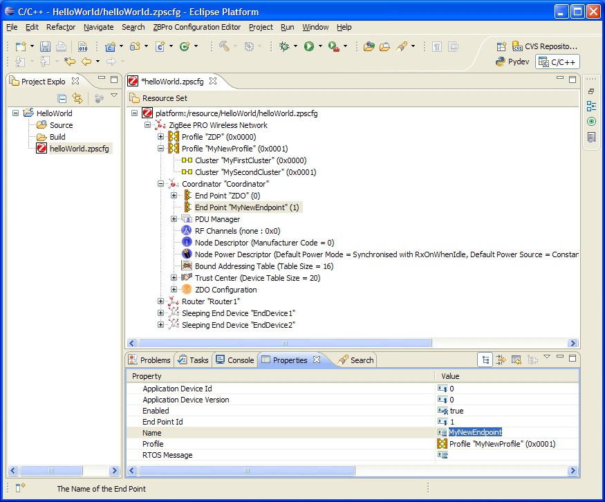
Step 1: Right-click on the Coordinator node and select New Child > End Point from the drop-down menu.
Step 2: Edit the properties in the Properties tab to set Name and Profile for the endpoint (the profile is selected from the drop-down box).
Step 3: Repeat Steps 1 and 2 for as many endpoints as are required.
Endpoint Properties
Parent topic:Setting Coordinator properties
To add an APDU
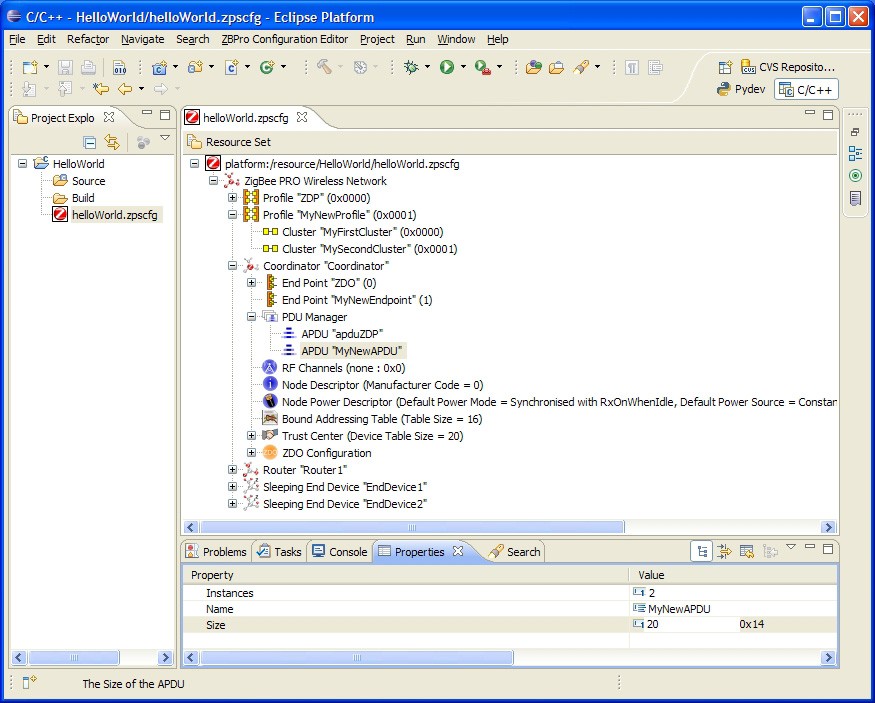
At least one APDU is required before an endpoint can send or receive data. The same APDU can be used to send and receive data, or different APDUs can be set up for send and receive - this allows control of buffering and memory resources, and is the decision of the application designer.
Step 1: Right-click on PDU Manager and select New Child > APDU from the drop-down menu.
Step 2: Edit the properties in the Properties tab to set Name, Instances (number of) and Size (of each instance - this should be set to the size of the largest APDU to be received).
Parent topic:Setting Coordinator properties
To add input and output clusters to an endpoint
To add input and output clusters to an endpoint
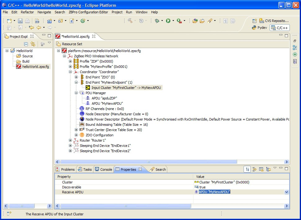
Step 1: Right-click on the endpoint and select New Child > Input Clusteror New Child > Output Cluster, as required, from the drop-down menu.
Step 2: Edit the properties in the Propertiestab to set Cluster- select from the available clusters in the drop-down list.
Step 3: Edit the Rx APDUor Tx APDUproperty to assign an APDU to the cluster - select from the available APDUs in the drop-down list.
To receive data, a cluster must have an assigned APDU. The same cluster can be both an input and output cluster, i.e. it will both send and receive data.
When an endpoint with an output cluster sends data, the receiving endpoint must have an input cluster in order to receive the data, otherwise the stack will reject it and will not notify the receiving endpoint. However, the Default cluster can be added to the endpoint in order to deal with received data that is destined for input clusters not supported by the endpoint (see the Note below this procedure).
Step 4: Repeat Step 1 to Step 3 to add as many clusters as are required for the endpoint.
Step 5: Repeat Step 1 to Step 4 for Routers and End Devices, as required.
Note: In the above procedure, you may want to add the Default cluster (with a Cluster ID of 0xFFFF) as an input cluster. The inclusion of the Default cluster means that received messages that were intended for input clusters not supported by the endpoint will still be passed to the application. The messages must, however, come from defined application profiles, otherwise they are discarded.
Parent topic:Setting Coordinator properties
Parent topic:Using the ZPS Configuration Editor