TwinCAT project setup
Import the EtherCAT Subdevice Information (ESI) file of the digital IO example.
Copy the ESI file named ‘ECAT-IO.xml’ generated by SSC tool from the SSC project folder to the <TwinCAT_installation_folder>/<Version>/Config/io/EtherCAT/ folder.
Create a new project.
Select File > New > Project.
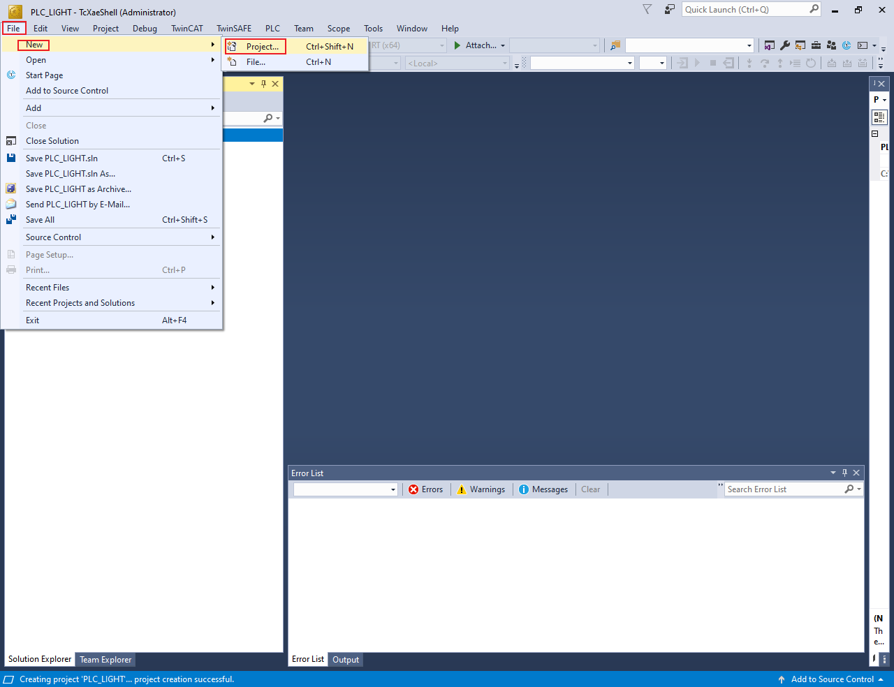
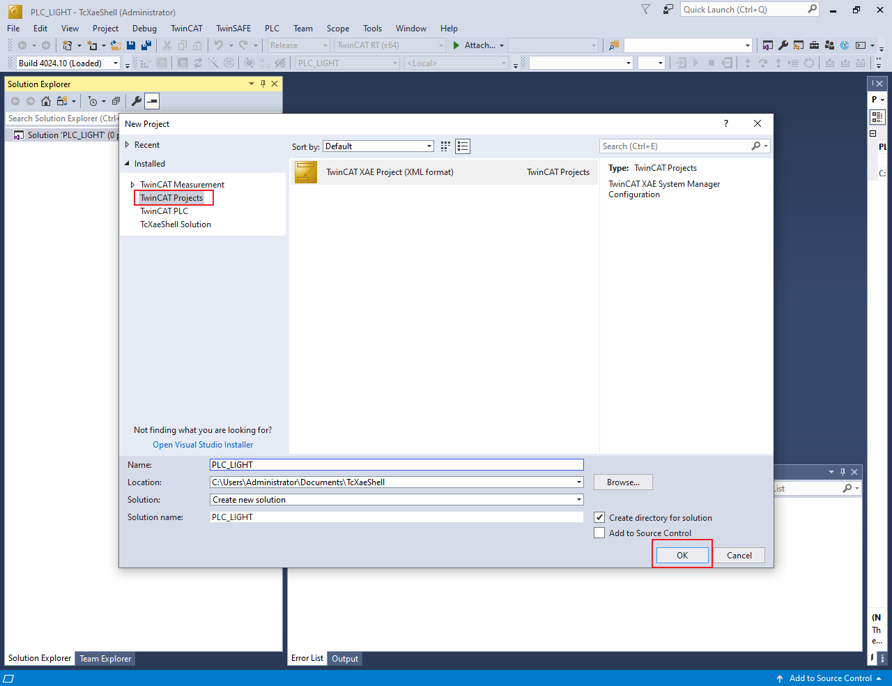
The New Project dialog box appears.
Select TwinCAT Projects.
Click OK.
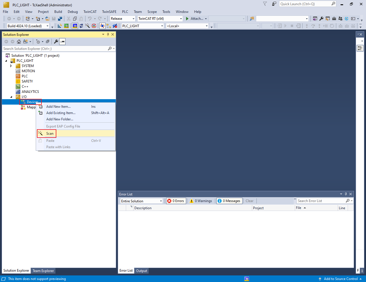
Scan the for subdevices.
In the Solution Explorer view, expand I/O.
Right-click on Device and select Scan.
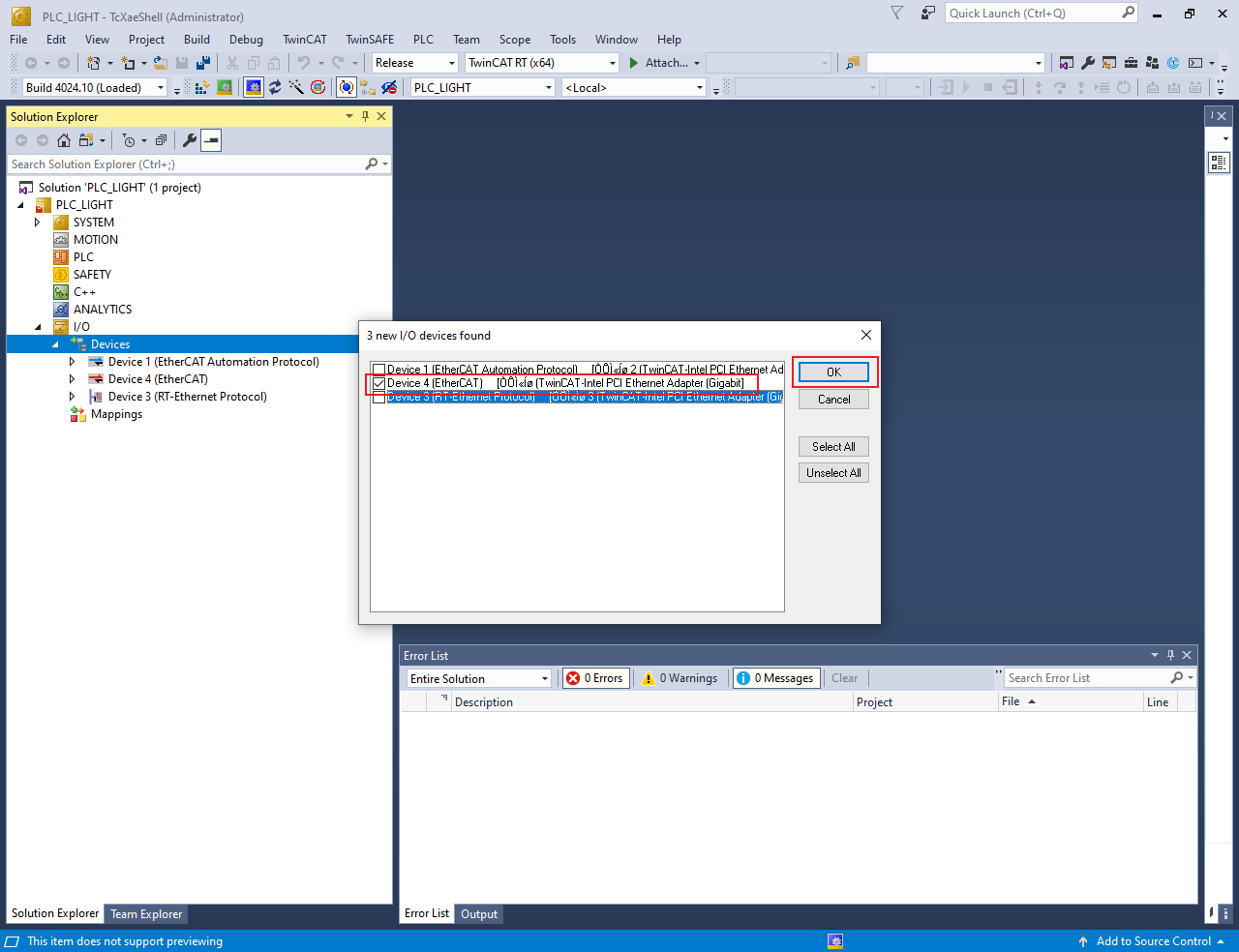
The scanned devices appear in the I/O devices found dialog box.
Select the network interface connected with the MIMXRT1180-EVK board.
Click OK.
Update the ESI file to E2PROM.
Note: The E2PROM must be updated if the digital IO example is set up first time on the MIMXRT1180-EVK.
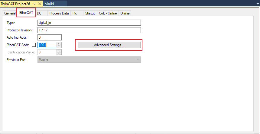
Under Device, double-click the EtherCAT device selected in step 4.The TwinCAT Project dialog box appears.
Click the EtherCAT tab.
Click the Advanced Settings button.
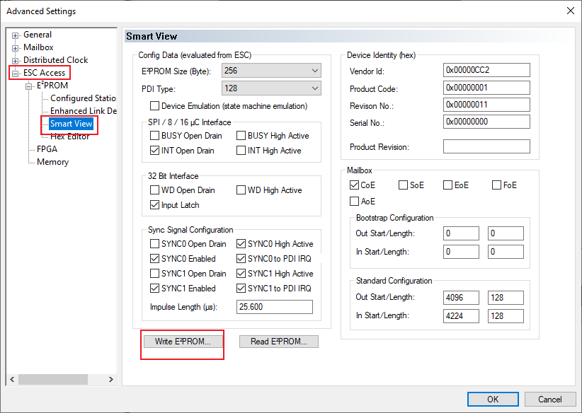
The Advanced Settings dialog box appears.
From the left pane of the Advanced Settings dialog box, select ESC Access > Smart View.
Click the Write E2PROM button.
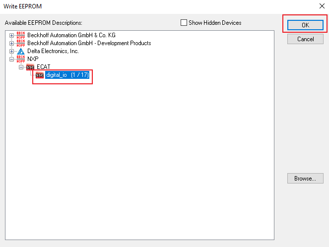
From the available EEPROM list, select NXP > ECAT > digital_io.
Click OK, delete Device4, rescan, and add Device4 after the success of the write EEPROM operation.
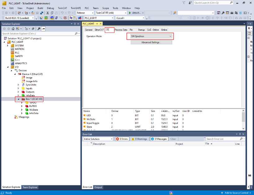
Configure the subdevice.
Click the DC tab.
From the Operation Mode field, select the SM-Synchron option.
Program the PLC code.
In the Solution Explorer view, right-click on PLC and select Add New Item.
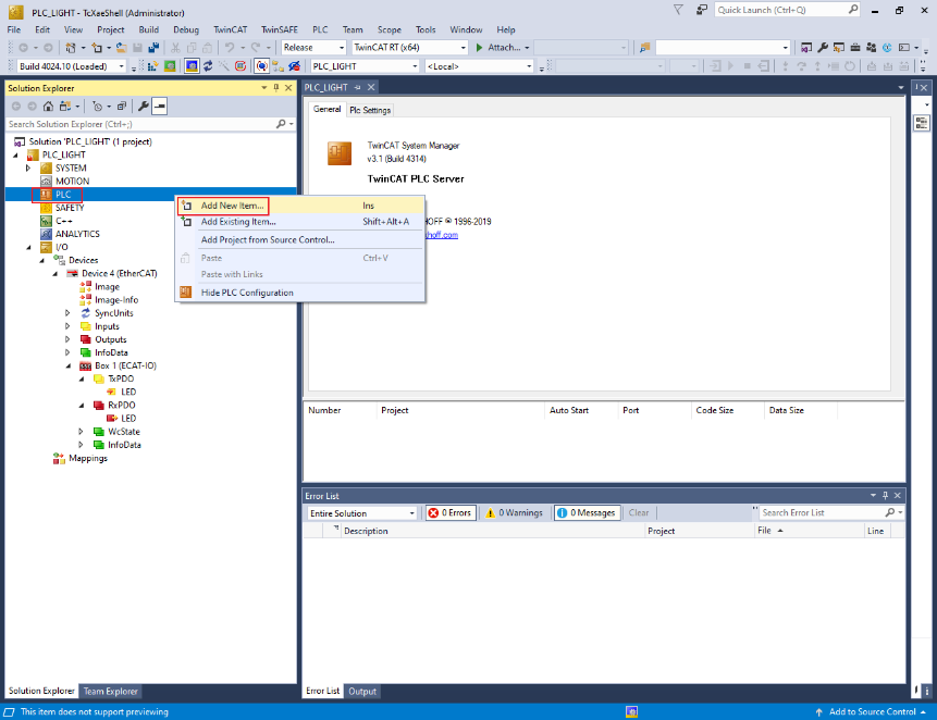
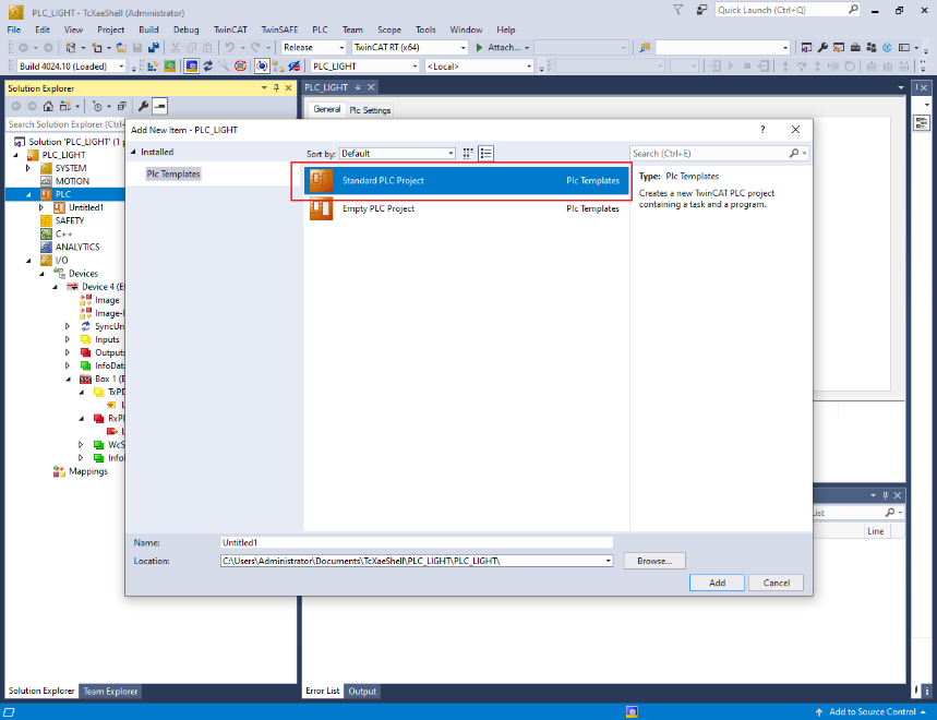
The Add New Item dialog box appears.
From the Installed list in the left pane, select Plc Templates.
Select Standard PLC Project.
Click OK.
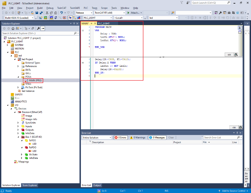
To open the PLC edit page, select MAIN (PRG) under PLC. See, Figure 11.
Copy the code below and paste it in the MAIN view. See, Figure 11.
PROGRAM MAIN
VAR
Delay : TON;
LedIn AT %I* : BOOL;
LedOut AT %Q* : BOOL;
END_VAR
Delay(IN := TRUE, PT := T#1S);
IF Delay.Q THEN
    LedOut := NOT LedIn;
    Delay(IN := FALSE);
END_IF;
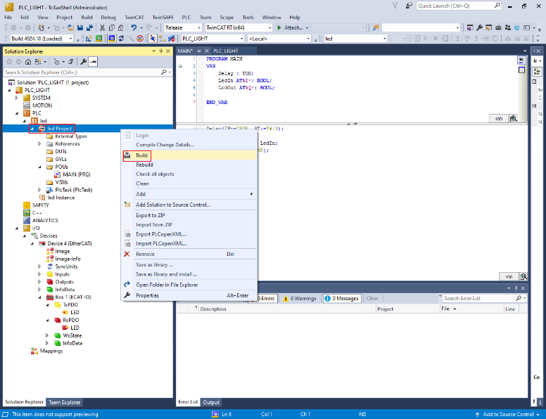
Build the PLC code.
Right-click on the PLC project and select Build.
Map the PLC variables to the subdevice IO channel.
Right-click on MAIN.LedIn, select Change Link. See, Figure 13.
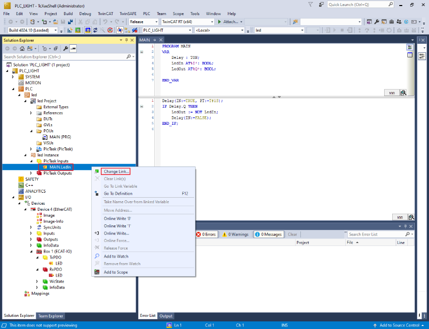
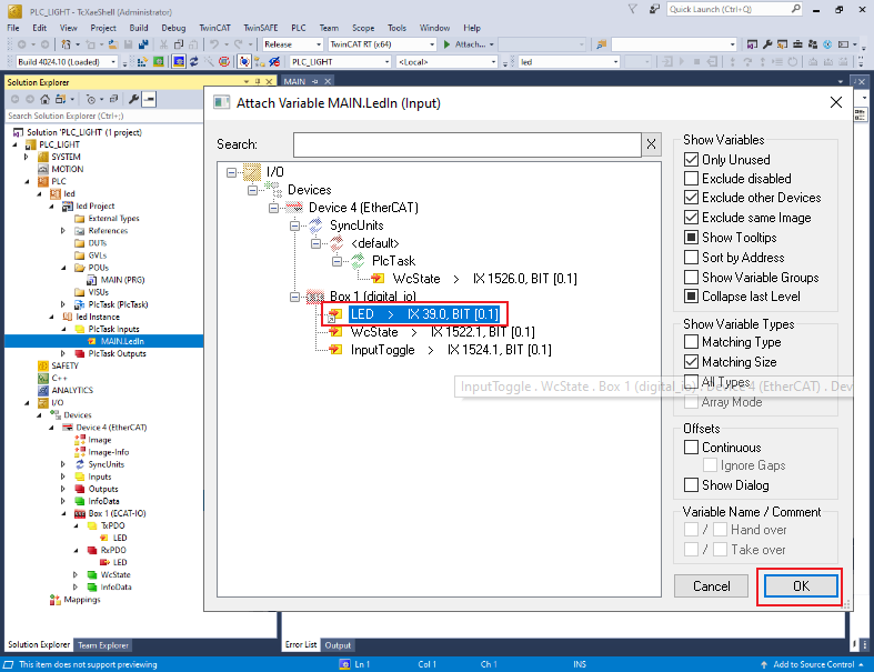
The Attach Variable MAIN.LedIn (Input) dialog box appears.
Select LED. See, Figure 14.
Click OK. See, Figure 14.
In the Solution Explorer, under PlcTask Outputs, right-click on MAIN.LedOut and select Change Link.
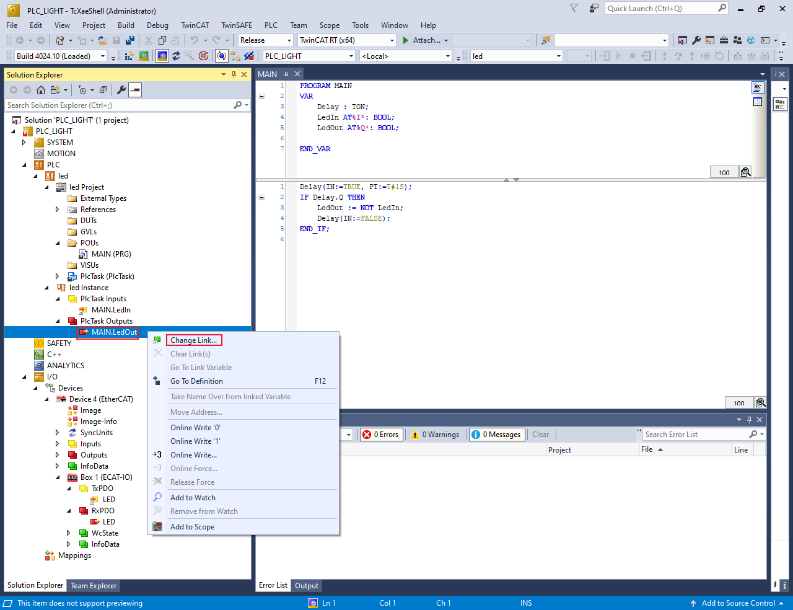
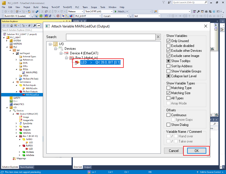
The Attach Variable MAIN.LedOut (Output) dialog box appears.
Select LED. See, Figure 16.
Click OK. See, Figure 16.
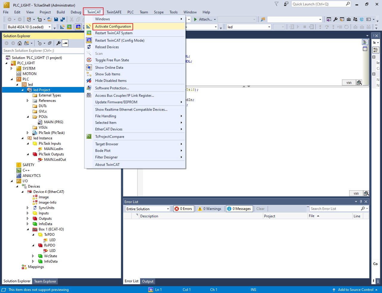
Run the PLC code.
To activate the configuration, select TwinCAT > Activate Configuration.
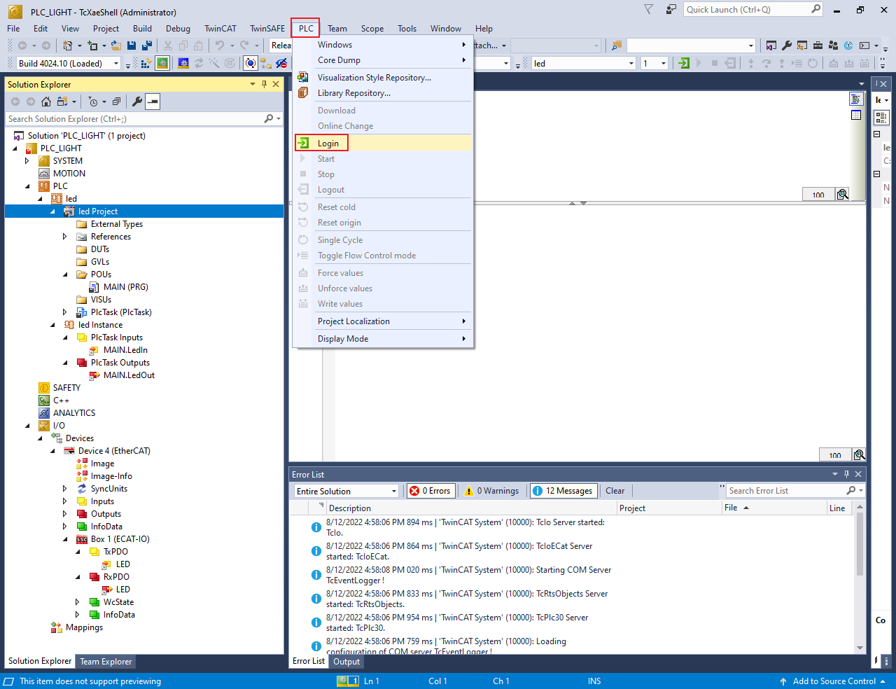
Select PLC > Login.
To initiate the PLC code, PLC > Start.
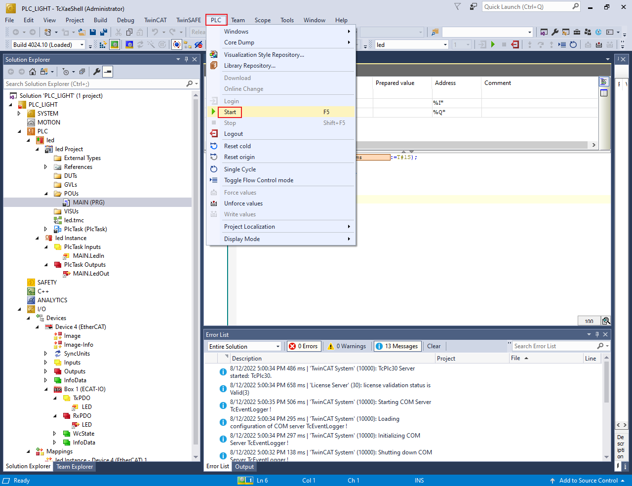
When the PLC code initiates, the D7 LED on the MIMXRT1180-EVK board starts blinking with 0.5 Hz frequency.