MCU bootloader command API
Introduction
All MCU bootloader command APIs follow the command packet format wrapped by the framing packet, as explained in the previous sections. See Table 4-9 for a list of commands supported by the MCU bootloader. For a list of status codes returned by the MCU bootloader, see Appendix A.
Parent topic:MCU bootloader protocol
Parent topic:MCU bootloader command API
GetProperty command
The GetProperty command is used to query the bootloader about various properties and settings. Each supported property has a unique 32-bit tag associated with it. The tag occupies the first parameter of the command packet. The target returns a GetPropertyResponse packet with the property values for the property identified with the tag in the GetProperty command.
The properties are the defined units of data that can be accessed with the GetProperty or SetProperty commands. The properties may be read-only or read-write. All read-write properties are 32-bit integers, so they can easily be carried in a command parameter.
For a list of properties and their associated 32-bit property tags supported by the MCU bootloader, see Appendix B, “GetProperty and SetProperty commands”.
The 32-bit property tag is the only parameter required for the GetProperty command.
Parameters for GetProperty command
Byte # |
Command |
|---|---|
0 - 3 |
Property tag |
4 - 7 |
External Memory Identifier (only applies to get property for external memory) |
Protocol sequence for GetProperty command

GetProperty Response Packet Format (Example)
GetProperty |
Parameter |
Value |
|---|---|---|
Framing packet |
start byte |
0x5A |
packetType |
0xA4, kFramingPacketType_Command |
|
length |
0x0C 0x00 |
|
crc16 |
0x4B 0x33 |
|
Command packet |
commandTag |
0x07 – GetProperty |
flags |
0x00 |
|
reserved |
0x00 |
|
parameterCount |
0x02 |
|
propertyTag |
0x00000001 - CurrentVersion |
|
Memory ID |
0x00000000 - Internal Flash (0x00000001 - QSPI0 Memory) |
The GetProperty command has no data phase.
Response: In response to a GetProperty command, the target sends a GetPropertyResponse packet with the response tag set to 0xA7. The parameter count indicates the number of parameters sent for the property values, with the first parameter showing the status code 0, followed by the property value(s). The following table shows an example of a GetPropertyResponse packet.
GetProperty Response Packet Format (Example)
GetPropertyResponse |
Parameter |
Value |
|---|---|---|
Framing packet |
start byte |
0x5A |
packetType |
0xA4, kFramingPacketType_Command |
|
length |
0x0c 0x00 (12 bytes) |
|
crc16 |
0xf4 9d |
|
Command packet |
responseTag |
0xA7 |
flags |
0x00 |
|
reserved |
0x00 |
|
parameterCount |
0x02 |
|
status |
0x00000000 |
|
propertyValue |
0x4b020600 - CurrentVersion |
Parent topic:MCU bootloader command API
SetProperty command
The SetProperty command is used to change or alter the values of the properties or options of the bootloader. The command accepts the same property tags used with the GetProperty command. However, only some properties are writable–see Appendix B. If an attempt to write a read-only property is made, an error is returned indicating that the property is read-only and cannot be changed.
The property tag and the new value to set are the two parameters required for the SetProperty command.
Parameters for SetProperty Command
Byte # |
Command |
|---|---|
0 - 3 |
Property tag |
4 - 7 |
Property value |
Protocol Sequence for SetProperty Command

SetProperty Command Packet Format (Example)
SetProperty |
Parameter |
Value |
|---|---|---|
Framing packet |
start byte |
0x5A |
packetType |
0xA4, kFramingPacketType_Command |
|
length |
0x0C 0x00 |
|
crc16 |
0x67 0x8D |
|
Command packet |
commandTag |
0x0C – SetProperty with property tag 10 |
flags |
0x00 |
|
reserved |
0x00 |
|
parameterCount |
0x02 |
|
propertyTag |
0x0000000A - VerifyWrites |
|
propertyValue |
0x00000001 |
The SetProperty command has no data phase.
Response: The target returns a GenericResponse packet with one of the following status codes:
SetProperty Response Status Codes
Status Code |
|---|
kStatus_Success |
kStatus_ReadOnly |
kStatus_UnknownProperty |
kStatus_InvalidArgument |
Parent topic:MCU bootloader command API
FlashEraseAll command
The FlashEraseAll command performs an erase of the entire flash memory. If any flash regions are protected, then the FlashEraseAll command fails and returns an error status code. Executing the FlashEraseAll command releases the flash security. The flash security is enabled by setting the FTFA_FSEC register. However, the FSEC field of the flash configuration field is erased, so unless it is reprogrammed, the flash security is re-enabled after the next system reset. The Command tag for the FlashEraseAll command is 0x01, set in the commandTag field of the command packet.
The FlashEraseAll command requires memory ID. If the memory ID is not specified, the internal flash (memory ID =0) is selected as default.
Protocol Sequence for FlashEraseAll Command

FlashEraseAll Command Packet Format (Example)
FlashEraseAll |
Parameter |
Value |
|---|---|---|
Framing packet |
start byte |
0x5A |
packetType |
0xA4, kFramingPacketType_Command |
|
length |
0x08 0x00 |
|
crc16 |
0x0C 0x22 |
|
Command packet |
commandTag |
0x01 - FlashEraseAll |
flags |
0x00 |
|
reserved |
0x00 |
|
parameterCount |
0x01 |
|
Memory ID |
0x00000000 - Internal Flash ( 0x00000001 - QSPI0 Memory) |
The FlashEraseAll command has no data phase.
Response: The target returns a GenericResponse packet with the status code set to kStatus_Success for a successful execution of the command, or set to an appropriate error status code.
Parent topic:MCU bootloader command API
FlashEraseRegion command
The FlashEraseRegion command performs an erase of one or more sectors of the flash memory.
The start address and number of bytes are the two parameters required for the FlashEraseRegion command. The start and byte count parameters must be 4-byte aligned ([1:0] = 00), or the FlashEraseRegion command fails and returns kStatus_FlashAlignmentError(101). If the region specified does not fit into the flash memory space, the FlashEraseRegion command fails and returns kStatus_FlashAddressError(102). If any part of the region specified is protected, the FlashEraseRegion command fails and returns kStatus_MemoryRangeInvalid(10200).
Parameters for FlashEraseRegion Command
Byte # |
Parameter |
|---|---|
0 - 3 |
Start address |
4 - 7 |
Byte count |
8 - 11 |
Memory ID |
The FlashEraseRegion command has no data phase.
Response: The target returns a GenericResponse packet with one of the following error status codes.
FlashEraseRegion Response Status Codes
Status Code |
|---|
kStatus_Success (0) |
kStatus_MemoryRangeInvalid (10200) |
kStatus_FlashAlignmentError (101) |
kStatus_FlashAddressError (102) |
kStatus_FlashAccessError (103) |
kStatus_FlashProtectionViolation (104) |
kStatus_FlashCommandFailure (105) |
Parent topic:MCU bootloader command API
FlashEraseAllUnsecure command
The FlashEraseAllUnsecure command performs a mass erase of the flash memory, including the protected sectors. The flash security is immediately disabled if it (flash security) was enabled, and the FSEC byte in the flash configuration field at address 0x40C is programmed to 0xFE. However, if the mass erase enable option in the FSEC field is disabled, then the FlashEraseAllUnsecure command fails.
The FlashEraseAllUnsecure command requires no parameters.
Protocol Sequence for FlashEraseAllUnsecure Command

FlashEraseAllUnsecure Command Packet Format (Example)
FlashEraseAllUnsecure |
Parameter |
Value |
|---|---|---|
Framing packet |
start byte |
0x5A |
packetType |
0xA4, kFramingPacketType_Command |
|
length |
0x04 0x00 |
|
crc16 |
0xF6 0x61 |
|
Command packet |
commandTag |
0x0D - FlashEraseAllUnsecure |
flags |
0x00 |
|
reserved |
0x00 |
|
parameterCount |
0x00 |
The FlashEraseAllUnsecure command has no data phase.
Response: The target returns a GenericResponse packet with the status code either set to kStatus_Success for successful execution of the commandor set to an appropriate error status code.
Note: When the MEEN bit in the NVM FSEC register is cleared to disable the mass erase, the FlashEraseAllUnsecure command fails. FlashEraseRegion can be used instead, skipping the protected regions.
Parent topic:MCU bootloader command API
ReadMemory command
The ReadMemory command returns the contents of the memory at the given address for a specified number of bytes. This command can read any region of memory accessible by the CPU and is not protected by security.
The start address and the number of bytes are the two parameters required for the ReadMemory command.
Parameters for ReadMemory command
Byte |
Parameter |
Description |
|---|---|---|
0 - 3 |
Start address |
Start address of memory to read from |
4 - 7 |
Byte count |
Number of bytes to read and return to caller |
8 - 11 |
Memory ID |
Internal or external memory Identifier |
Command sequence for ReadMemory command

ReadMemory packet format example
ReadMemory |
Parameter |
Value |
|---|---|---|
Framing packet |
Start byte |
0x5A0xA4, |
packetType |
kFramingPacketType_Command |
|
length |
0x10 00 |
|
crc16 |
0xf4 1b |
|
Command packet |
commandTag |
0x03 - readMemory |
flags |
0x00 |
|
reserved |
0x00 |
|
parameterCount |
0x03 |
|
startAddress |
0x20000400 |
|
byteCount |
0x00000064 |
|
memoryID |
0x0 |
Data Phase: The ReadMemory command has a data phase. Because the target works in the slave mode, the host must pull the data packets until the number of bytes of data specified in the byteCount parameter of the ReadMemory command are received by the host.
Response: The target returns a GenericResponse packet with a status code either set to kStatus_Success upon a successful execution of the command, or set to an appropriate error status code.
Parent topic:MCU bootloader command API
WriteMemory command
The WriteMemory command writes the data provided in the data phase to a specified range of bytes in the memory (flash or RAM). However, if the flash protection is enabled, then the writes to the protected sectors fail.
Special care must be taken when writing to the flash.
First, any flash sector written to must be previously erased with the FlashEraseAll, FlashEraseRegion, or FlashEraseAllUnsecure command.
First, any flash sector written to must be previously erased with the FlashEraseAll or FlashEraseRegion command.
Writing to the flash requires the start address to be 4-byte aligned ([1:0] = 00).
The byte count is rounded up to a multiple of 4, and the trailing bytes are filled with the flash erase pattern (0xff).
If the VerifyWrites property is set to true, then the writes to the flash also perform a flash verify program operation.
When writing to the RAM, the start address does not need to be aligned, and the data is not padded.
The start address and the number of bytes are the two parameters required for the WriteMemory command.
Parameters for WriteMemory Command
Byte # |
Command |
|---|---|
0 - 3 |
Start address |
4 - 7 |
Byte count |
8 - 11 |
Memory ID |
Protocol Sequence for WriteMemory Command

WriteMemory Command Packet Format (Example)
WriteMemory |
Parameter |
Value |
|---|---|---|
Framing packet |
start byte |
0x5A |
packetType |
0xA4, kFramingPacketType_Command |
|
length |
0x10 00 |
|
crc16 |
0x97 DD |
|
Command packet |
commandTag |
0x04 - writeMemory |
flags |
0x01 |
|
reserved |
0x00 |
|
parameterCount |
0x03 |
|
startAddress |
0x20000400 |
|
byteCount |
0x00000064 |
|
memoryID |
0x0 |
Data Phase: The WriteMemory command has a data phase; the host sends data packets until the number of bytes of data specified in the byteCount parameter of the WriteMemory command are received by the target.
Response: The target returns the GenericResponse packet with a status code set to kStatus_Success upon a successful execution of the command, or to an appropriate error status code.
Parent topic:MCU bootloader command API
FillMemory command
The FillMemory command fills a range of bytes in the memory with a data pattern. It follows the same rules as the WriteMemory command. The difference between the FillMemory and the WriteMemory is that a data pattern is included in the FillMemory command parameter, and there is no data phase for the FillMemory command, while the WriteMemory command has a data phase.
Parameters for FillMemory Command
Byte # |
Command |
|---|---|
0 - 3 |
Start address of memory to fill |
4 - 7 |
Number of bytes to write with the pattern |
8 - 11 |
32-bit pattern |
To fill with a byte pattern (8-bit), the byte must be replicated four times in the 32-bit pattern.
To fill with a short pattern (16-bit), the short value must be replicated two times in the 32-bit pattern.
For example, to fill a byte value with 0xFE, the word pattern is 0xFEFEFEFE; to fill a short value 0x5AFE, the word pattern is 0x5AFE5AFE.
Special care must be taken when writing to the flash.
First, any flash sector written to must be previously erased with a FlashEraseAll, FlashEraseRegion, or FlashEraseAllUnsecure command.
First, any flash sector written to must be previously erased with a FlashEraseAll or FlashEraseRegion command.
Writing to the flash requires the start address to be 4-byte aligned ([1:0] = 00).
If the VerifyWrites property is set to true, then a write to the flash also performs a flash verify program operation.
When writing to the RAM, the start address does not need to be aligned, and the data is not padded.
Protocol Sequence for FillMemory Command

FillMemory Command Packet Format (Example)
FillMemory |
Parameter |
Value |
|---|---|---|
Framing packet |
start byte |
0x5A |
packetType |
0xA4, kFramingPacketType_Command |
|
length |
0x10 0x00 |
|
crc16 |
0xE4 0x57 |
|
Command packet |
commandTag |
0x05 – FillMemory |
flags |
0x00 |
|
Reserved |
0x00 |
|
parameterCount |
0x03 |
|
startAddress |
0x00007000 |
|
byteCount |
0x00000800 |
|
patternWord |
0x12345678 |
The FillMemory command has no data phase.
Response: upon a successful execution of the command, the target (MCU bootloader) returns a GenericResponse packet with a status code set to kStatus_Success, or to an appropriate error status code.
Parent topic:MCU bootloader command API
FlashSecurityDisable command
The FlashSecurityDisable command performs the flash security disable operation by comparing the 8-byte backdoor key (provided in the command) against the backdoor key stored in the flash configuration field (at address 0x400 in the flash).
The backdoor low and high words are the only parameters required for the FlashSecurityDisable command.
Parameters for FlashSecurityDisable Command
Byte # |
Command |
|---|---|
0 - 3 |
Backdoor key low word |
4 - 7 |
Backdoor key high word |
Protocol Sequence for FlashSecurityDisable Command

FlashSecurityDisable Command Packet Format (Example)
FlashSecurityDisable |
Parameter |
Value |
|---|---|---|
Framing packet |
start byte |
0x5A |
packetType |
0xA4, kFramingPacketType_Command |
|
length |
0x0C 0x00 |
|
crc16 |
0x43 0x7B |
|
Command packet |
commandTag |
0x06 - FlashSecurityDisable |
flags |
0x00 |
|
reserved |
0x00 |
|
parameterCount |
0x02 |
|
Backdoorkey_low |
0x04 0x03 0x02 0x01 |
|
Backdoorkey_high |
0x08 0x07 0x06 0x05 |
The FlashSecurityDisable command has no data phase.
Response: The target returns a GenericResponse packet with a status code either set to kStatus_Success upon a successful execution of the command, or set to an appropriate error status code.
Parent topic:MCU bootloader command API
Execute command
The execute command results in the bootloader setting the program counter to the code at the provided jump address, R0 to the provided argument, and a Stack pointer to the provided stack pointer address. Before the jump, the system is returned to the reset state.
The Jump address, function argument pointer, and stack pointer are the parameters required for the Execute command. If the stack pointer is set to zero, the called code is responsible for setting the processor stack pointer before using the stack.
If the QSPI is enabled, it is initialized before the jump. The QSPI encryption (OTFAD) is also enabled (if configured).
Parameters for Execute Command
Byte # |
Command |
|---|---|
0 - 3 |
Jump address |
4 - 7 |
Argument word |
8 - 11 |
Stack pointer address |
The Execute command has no data phase.
Response: Before executing the Execute command, the target validates the parameters and returns a GenericResponse packet with a status code either set to kStatus_Success or an appropriate error status code.
Parent topic:MCU bootloader command API
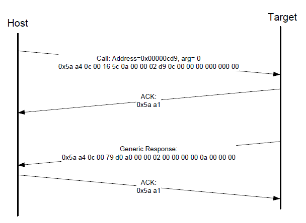
Call command
The Call command executes a function that is written in the memory at the address sent in the command. The address must be be a valid memory location residing in the accessible flash (internal or external) or in the RAM. The command supports the passing of one 32-bit argument. Although the command supports a stack address, at this time, the call still takes place using the current stack pointer. After the execution of the function, a 32-bit return value is returned in the generic response message.
The QSPI must be initialized before executing the Call command if the call address is on the QSPI. The Call command does not initialize the QSPI.
Protocol sequence for call command
Parameters for Call Command
Byte # |
Command |
|---|---|
0 - 3 |
Call address |
4 - 7 |
Argument word |
8 - 11 |
Stack pointer |
Response: The target returns a GenericResponse packet with a status code either set to the return value of the function called or set to kStatus_InvalidArgument (105).
Parent topic:MCU bootloader command API
Reset command
The Reset command results in the bootloader resetting the chip.
The Reset command requires no parameters.
Protocol Sequence for Reset Command

Reset Command Packet Format (Example)
Reset |
Parameter |
Value |
|---|---|---|
Framing packet |
start byte |
0x5A |
packetType |
0xA4, kFramingPacketType_Command |
|
length |
0x04 0x00 |
|
crc16 |
0x6F 0x46 |
|
Command packet |
commandTag |
0x0B - reset |
flags |
0x00 |
|
reserved |
0x00 |
|
parameterCount |
0x02 |
The Reset command has no data phase.
Response: The target returns a GenericResponse packet with a status code set to kStatus_Success before resetting the chip.
The Reset command can also be used to switch the boot from the flash after a successful flash image provisioning via the ROM bootloader. After issuing the reset command, wait five seconds for the user application to start running from the flash.
Parent topic:MCU bootloader command API
FlashProgramOnce command
The FlashProgramOnce command writes the data (that is provided in a command packet) to a specified range of bytes in the program once field. Special care must be taken when writing to the program once field.
The program once field only supports programming once, so any attempts to reprogram a program once field get an error response.
Writing to the program once field requires the byte count to be 4-byte aligned or 8-byte aligned.
The FlashProgramOnce command uses three parameters: index 2, byteCount, data.
Parameters for FlashProgramOnce Command
Byte # |
Command |
|---|---|
0 - 3 |
Index of program once field |
4 - 7 |
Byte count (must be evenly divisible by 4) |
8 - 11 |
Data |
12 - 16 |
Data |
Protocol Sequence for FlashProgramOnce Command

FlashProgramOnce Command Packet Format (Example)
FlashProgramOnce |
Parameter |
Value |
|---|---|---|
Framing packet |
start byte |
0x5A |
packetType |
0xA4, kFramingPacketType_Command |
|
length |
0x10 0x00 |
|
crc16 |
0x7E4 0x89 |
|
Command packet |
commandTag |
0x0E – FlashProgramOnce |
flags |
0 |
|
reserved |
0 |
|
parameterCount |
3 |
|
index |
0x0000_0000 |
|
byteCount |
0x0000_0004 |
|
data |
0x1234_5678 |
Response: upon a successful execution of the command, the target (MCU bootloader) returns a GenericResponse packet with a status code set to kStatus_Success, or to an appropriate error status code.
Parent topic:MCU bootloader command API
FlashReadOnce command
The FlashReadOnce command returns the contents of the program once field by the given index and byte count. The FlashReadOnce command uses two parameters: index and byteCount.
Parameters for FlashReadOnce Command
Byte # |
Parameter |
Description |
|---|---|---|
0 - 3 |
index |
Index of the program once field (to read from) |
4 - 7 |
byteCount |
Number of bytes to read and return to the caller |
Protocol Sequence for FlashReadOnce Command

FlashReadOnce Command Packet Format (Example)
FlashReadOnce |
Parameter |
Value |
|---|---|---|
Framing packet |
start byte |
0x5A |
packetType |
0xA4 |
|
length |
0x0C 0x00 |
|
crc |
0xC1 0xA5 |
|
Command packet |
commandTag |
0x0F – FlashReadOnce |
flags |
0x00 |
|
reserved |
0x00 |
|
parameterCount |
0x02 |
|
index |
0x0000_0000 |
|
byteCount |
0x0000_0004 |
FlashReadOnce Response Format (Example)
FlashReadOnce Response |
Parameter |
Value |
|---|---|---|
Framing packet |
start byte |
0x5A |
packetType |
0xA4 |
|
length |
0x10 0x00 |
|
crc |
0x3F 0x6F |
|
Command packet |
commandTag |
0xAF |
flags |
0x00 |
|
reserved |
0x00 |
|
parameterCount |
0x03 |
|
status |
0x0000_0000 |
|
byteCount |
0x0000_0004 |
|
data |
0x1234_5678 |
Response: upon a successful execution of the command, the target returns a FlashReadOnceResponse packet with a status code set to kStatus_Success, a byte count and corresponding data read from the Program Once Field upon a successful execution of the command, or a status code set to an appropriate error status code and a byte count set to 0.
Parent topic:MCU bootloader command API
FlashReadResource command
The FlashReadResource command returns the contents of the IFR field or the Flash firmware ID by the given offset, byte count, and option. The FlashReadResource command uses three parameters: start address, byteCount, and option.
Parameters for FlashReadResource Command
Byte # |
Parameter |
Command |
|---|---|---|
0 - 3 |
start address |
Start address of specific non-volatile memory to be read |
4 - 7 |
byteCount |
Byte count to be read |
8 - 11 |
option |
0: IFR |
Protocol Sequence for FlashReadResource Command

FlashReadResource Command Packet Format (Example)
FlashReadResource |
Parameter |
Value |
|---|---|---|
Framing packet |
start byte |
0x5A |
packetType |
0xA4 |
|
length |
0x10 0x00 |
|
crc |
0xB3 0xCC |
|
Command packet |
commandTag |
0x10 – FlashReadResource |
flags |
0x00 |
|
reserved |
0x00 |
|
parameterCount |
0x03 |
|
startAddress |
0x0000_0000 |
|
byteCount |
0x0000_0008 |
|
option |
0x0000_0001 |
FlashReadResource Response Format (Example)
FlashReadResource Response |
Parameter |
Value |
|---|---|---|
Framing packet |
start byte |
0x5A |
packetType |
0xA4 |
|
length |
0x0C 0x00 |
|
crc |
0xD2 0xB0 |
|
Command packet |
commandTag |
0xB0 |
flags |
0x01 |
|
reserved |
0x00 |
|
parameterCount |
0x02 |
|
status |
0x0000_0000 |
|
byteCount |
0x0000_0008 |
Data phase: The FlashReadResource command has a data phase. Because the target (MCU bootloader) works in a slave mode, the host must pull the data packets until the number of bytes of data specified in the byteCount parameter of FlashReadResource command is received by the host.
Parent topic:MCU bootloader command API
Configure Memory command
The Configure Memory command configures the external memory device using a pre-programmed configuration image. The parameters passed in the command are the memory ID (which should be 1 QuadSPI Nor Memory) and the memory address from which the configuration data can be loaded from. The options for loading the data can be a scenario where the configuration data is written to a RAM or flash location and this command directs the bootloader to use the data at that location to configure the external memory devices.
Parameters for Configure QuadSPI Command
Byte # |
Command |
|---|---|
0 – 3 |
Memory ID |
4 – 7 |
Configuration block address |
Response: The target (MCU bootloader) returns a GenericResponse packet with a status code either set to kStatus_Success upon a successful execution of the command, or set to an appropriate error code.
Parent topic:MCU bootloader command API
ReceiveSBFile command
The ReceiveSBFile command starts the transfer of an SB file to the target. The command only specifies the size of the SB file that is sent in the data phase (in bytes). The SB file is processed as it is received by the bootloader.
Parameters for ReceiveSBFile Command
Byte # |
Command |
|---|---|
0 - 3 |
Byte count |
Data Phase: The ReceiveSBFile command has a data phase. The host sends data packets until the number of bytes of data specified in the byteCount parameter of the ReceiveSBFile command are received by the target.
Response: The target returns a GenericResponse packet with a status code set to kStatus_Success upon a successful execution of the command or set to an appropriate error code.
Parent topic:MCU bootloader command API
ReliableUpdate command
The ReliableUpdate command performs the reliable update operation.
For a software implementation: the backup application address is the parameter that is required for the ReliableUpdate command. If the backup address is set to 0, then the bootloader uses the predefined address.
For a hardware implementation: the swap indicator address is the parameter that is required for the ReliableUpdate command.
If the flash swap system is uninitialized, then the swap indicator address can be arbitrarily specified.
If the flash swap system is initialized, then the swap indicator must be aligned with the swap system.
Parameters for ReliableUpdate command
Byte number |
Command |
|---|---|
0 - 3 |
- For a software implementation: the value is the backup application address. |
**Response:**The target returns a GenericResponse packet with a status code either set to kStatus_Success upon a successful execution of the command, or set to an appropriate error status code.
Parent topic:MCU bootloader command API