Primary porting tasks
After the basic file structure and source files are in place, the porting work can begin. This section describes which files need to be modified and how to modify them.
Bootloader peripherals
The bootloader source uses a C/C++ preprocessor define to configure the bootloader based on the target device. Update this define to reference the correct set of device-specific header files.
Options for node “freedom_bootloader” 
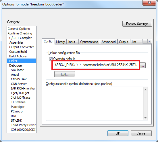
If the memory configuration of the target device differs from the closest match, the linker file must be replaced. Refer to linker files in devices/<device>/<tool chain> and update it as per the bootloader project. Update the linker settings via the project options.
Porting guide change linker file
Supported peripherals
The bootloader uses the peripherals_<device>.c file to define which peripheral interfaces are active in the bootloader. The source file includes a single table, g_peripherals[], that contains active peripheral information and pointers to configuration structures. This file is found in middleware/mcu-boot/targets/<device>/src.
Only place configurations for peripherals that are present on the target device. Otherwise, the processor generates fault conditions when trying to initialize a peripheral that is not physically present.
For the content of each entry in the g_peripherals[] table, reuse existing entries and only modify the .instance member. For example, starting with the following UART0 member, make the change to UART1 by simply changing .instance from “0” to “1”.
{
      .typeMask = kPeripheralType_UART,
      .instance = 0,
      .pinmuxConfig = uart_pinmux_config,
      .controlInterface = &g_scuartControlInterface;
      .byteInterface = &g_scuartByteInterfacek;
      .packetInterface = &g_framingPacketInterface;
}
When the table has all required entries, it must be terminated with a null { 0 } entry.
Parent topic:Bootloader peripherals
Peripheral initialization
After the peripheral configuration has been selected, the low-level initialization must be accounted for. The bootloader automatically enables the clock and configures the peripheral, so the only thing required for the port is to tell the bootloader which pins to use for each peripheral. This is handled in the peripherals_pinmux.h file in middleware/ mcu-boot/targets/<device>/src. The hardware_init_<device>.c file selects the boot pin used by the bootloader, which may need to be changed for the new target device.
These files most likely require significant changes to account for the differences between devices when it comes to pin routing. Each function should be checked for correctness and modified as needed.
Parent topic:Bootloader peripherals
Clock initialization
The MCU bootloader typically uses the device default clock configuration in order to avoid dependencies on external components and simplify use. In some situations, the default clock configuration cannot be used due to accuracy requirements of supported peripherals. On devices that have on-chip USB and CAN, the default system configuration is not suficient and the bootloader configures the device to run from the high-precision internal reference clock (IRC) if available. Otherwise, it depends on the external oscillator supply.
The bootloader uses the clock_config_<device>.c file in middleware/mcu-boot/targets/ <device>/src to override the default clock behavior. If the port’s target device supports USB, this file can be used. If the port’s target device does not support USB, the functions within clock_config_<device>.c can be stubbed out or set to the required port value.
Parent topic:Bootloader peripherals
Parent topic:Primary porting tasks
Bootloader configuration
Configure the bootloader to match the supported features and the specific memory map for the target device. Turn features on or off by using #define statements in the bootloader_config.h file in middleware/mcu-boot/targets/<device>/src. See examples for using these macros in bl_command.c (g_commandHandlerTable[] table) in the middleware/mcu-boot/src/bootloader/src folder. All checks that reference a BL_* feature can be turned on or off. Examples of these features are BL_MIN_PROFILE, BL_HAS_MASS_ERASE, and BL_FEATURE_READ_MEMORY.
One of the most important bootloader configuration choices is where to set the start address (vector table) of the user application. This is determined by the BL_APP_VECTOR_TABLE_ADDRESS define in bootloader_config.h. Most bootloader configurations choose to place the user application at address 0xA000 because that accommodates the full-featured bootloader image. It is possible to move this start address if the resulting port reduces features (and therefore, code size) of the bootloader.
Note: Load the Release build of the flash-resident bootloader if you plan to place the user application at 0xA000. Loading the Debug build requires you to move the application address beyond the end of the bootloader image. This address can be determined from the bootloader map file.
Parent topic:Primary porting tasks
Bootloader memory map configuration
The MCU device memory map and flash configuration must be defined for proper operation of the bootloader. The device memory map is defined in the g_memoryMap[] structure of the memory_map_<device>.c file, which can be found in middleware/mcu-boot/targets/<device>/src. An example memory map configuration is shown.
memory_map_entry_t g_memoryMap[] =
{
    {0x00000000,0x000fffff, kMemoryIsExecutable, &g_flashMemoryInterface},   // Flash array (1024KB)
    {0x1fff0000,0x2002ffff, kMemoryIsExecutable, &g_normalMemoryInterface},  // SRAM (256KB)
    {0x40000000,0x4007ffff, kMemoryNotExecutable, &g_deviceMemoryInterface},// AIPS peripherals
    {0x400ff000,0x400fffff, kMemoryNotExecutable, &g_deviceMemoryInterface}, // GPIO
    {0xe0000000,0xe00fffff, kMemoryNotExecutable, &g_deviceMemoryInterface},// M4 private peripherals
    {0}                                                                                                                    // Terminator
};
In addition to the device memory map, the correct SRAM initialization file must be selected according to the target device. This file is split based on ARM® Cortex®-M4 and Cortex-M0+ based devices, so the likelihood of having to change it is low.
The sram_init_cm4.c file is located in middleware/mcu-boot/src/memory/src for M4 devices and sram_init_cm0plus.c for M0+ devices.
Parent topic:Primary porting tasks
Parent topic:MCU bootloader porting