TwinCAT project setup
Import the EtherCAT Subdevice Information (ESI) file of the EoE example.
Copy the ESI file named ‘ECAT-EOE.xml’ generated by SSC tool from the SSC project folder to the <TwinCAT_installation_folder>/<Version>/Config/io/EtherCAT/ folder.
Create a new project.
Select File > New > Project.
The New Project dialog box appears.
Select TwinCAT Projects.
Click OK.
Scan the for subdevices.
In the Solution Explorer view, expand I/O.
Right-click on Device and select Scan.
The scanned devices appear in the I/O devices found dialog box.
Select the network interface connected with the MIMXRT1180-EVK board.
Click OK.
Update the ESI file to E2PROM.
Note: The E2PROM must be updated if the EOE example is set up first time on the MIMXRT1180-EVK.
Under Device, double-click Box1.The TwinCAT Project dialog box appears.
Click the EtherCAT tab.
Click the Advanced Settings button.
The Advanced Settings dialog box appears.
From the left pane of the Advanced Settings dialog box, select ESC Access > Smart View.
Click the Write E2PROM button.
From the available EEPROM list, select NXP > ECAT > eoe_freertos.
Click OK, delete Device4, rescan, and add Device4 after the write EEPROM operation is successful.
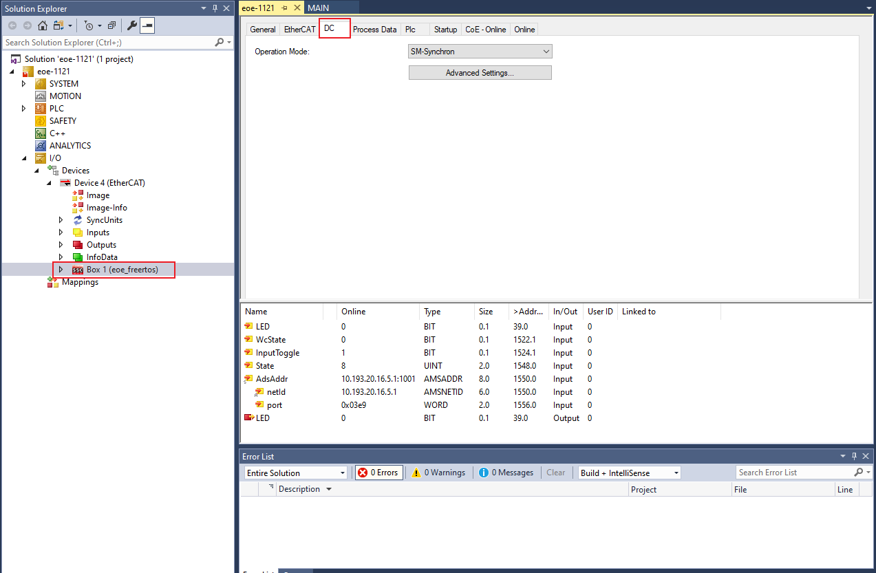
Configure the subdevice.
Click the DC tab.
From the Operation Mode field, select the SM-Synchron or DC option.
Program the PLC code.
In the Solution Explorer view, right-click on PLC and select Add New Item.
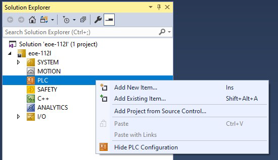
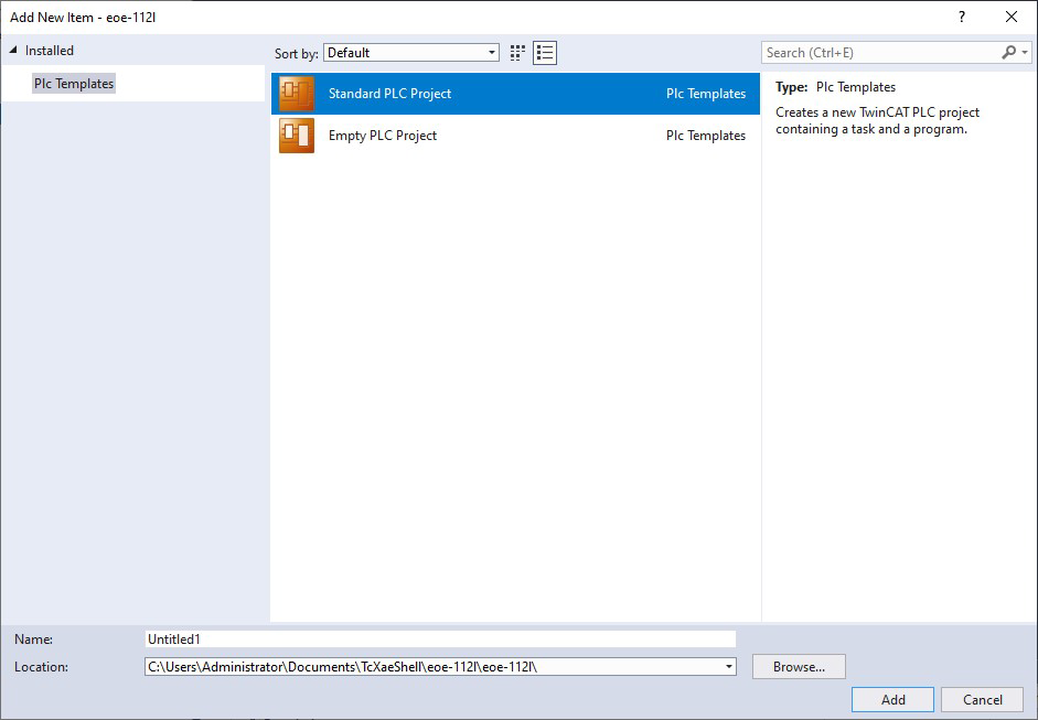
The Add New Item dialog box appears.
From the Installed list in the left pane, select PLC Templates.
Select Standard PLC Project.
Click OK.
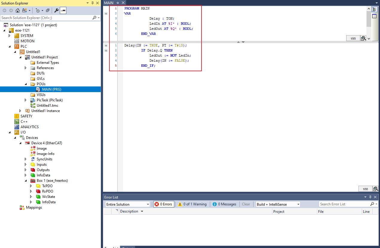
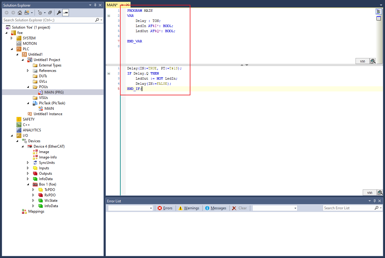
To open the PLC edit page, select MAIN (PRG) under PLC.
Copy the code below and paste it in the MAIN view.
PROGRAM MAIN
                VAR
                Delay : TON;
                LedIn AT %I* : BOOL;
                LedOut AT %Q* : BOOL;
                END_VAR
Delay(IN := TRUE, PT := T#1S);
IF Delay.Q THEN
    LedOut := NOT LedIn;
    Delay(IN := FALSE);
 END_IF;
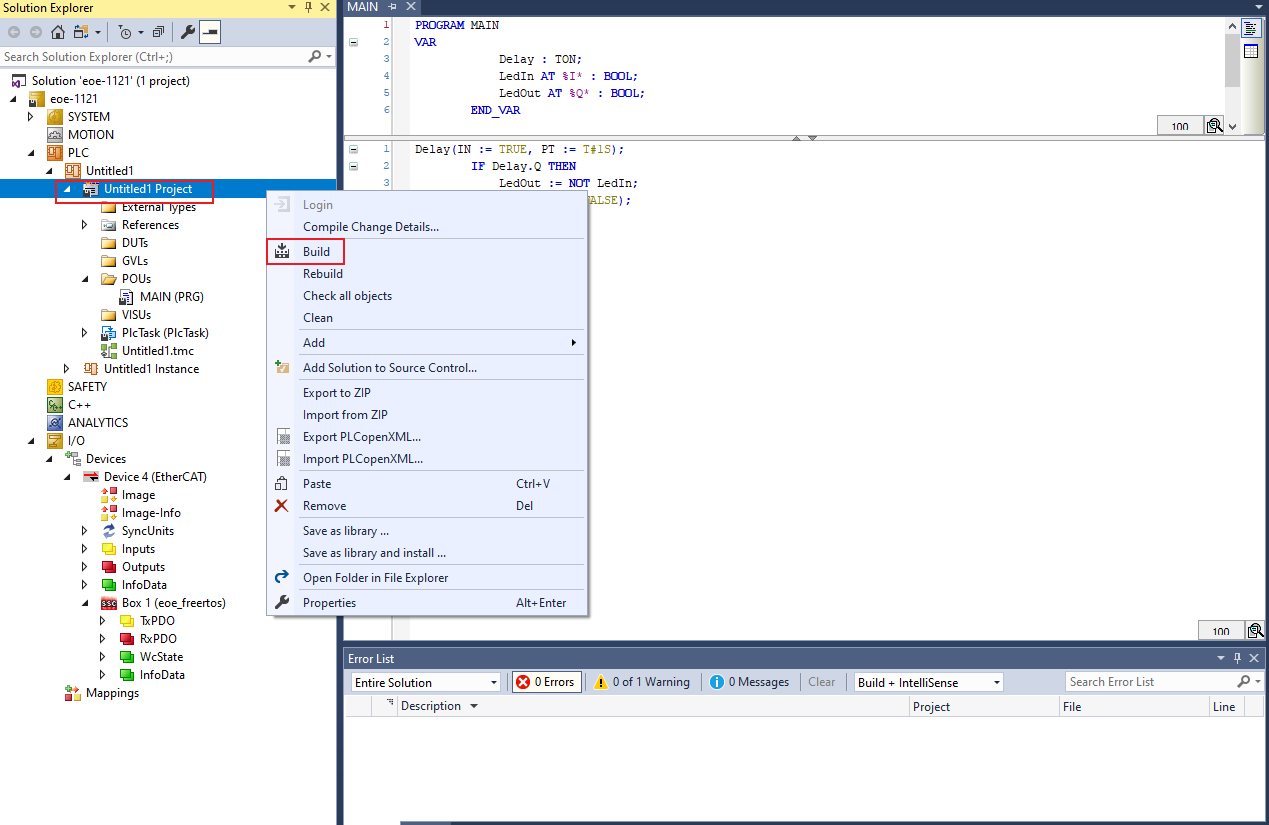
Build the PLC code.
Right-click on the PLC project and select Build.
Map the PLC variables to the subdevice IO channel.
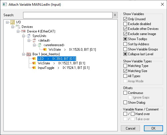
Right-click on MAIN.LedIn, select Change Link.
The Attach Variable MAIN.LedIn (Input) dialog box appears.
Select LED. .
Click OK.
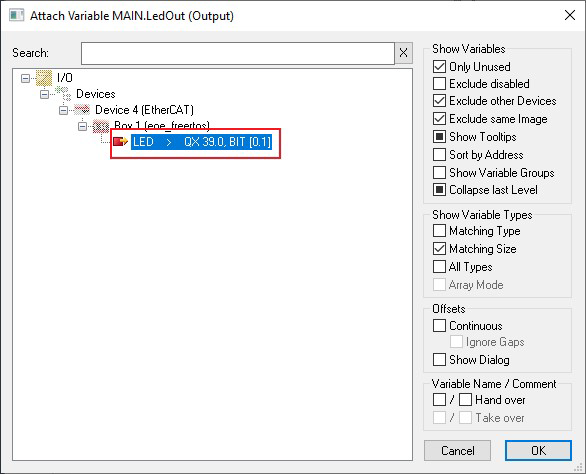
In the Solution Explorer, under PlcTask Outputs, right-click on MAIN.LedOut and select Change Link.
The Attach Variable MAIN.LedOut (Output) dialog box appears.
Select LED.
Click OK.
Configure the PC IP address.
ip address: 192.168.1.102subnet mask: 255.255.255.0gateway: 192.168.1.0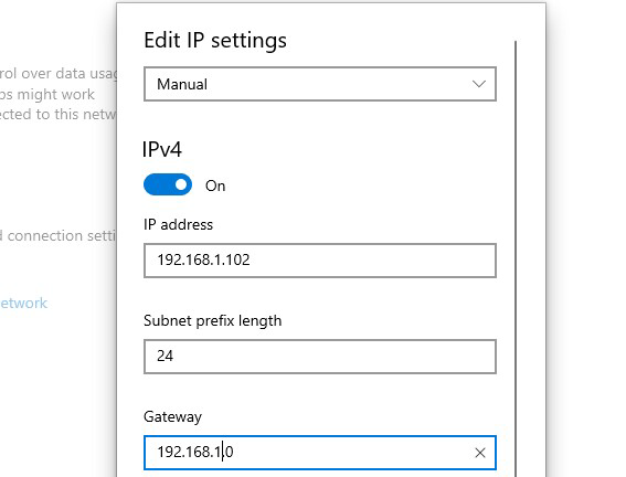
Configure the board IP address.
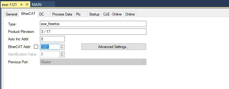
Under Device, double-click **Box1.**The TwinCAT Project dialog box appears.
Click the EtherCAT tab.
Click the Advanced Settings button.
The Advanced Settings dialog box appears.
Click Mailbox > EOE > IP Port.
Set the address of the board.
ip address: 192.168.1.66subnet mask: 255.255.255.0gateway: 192.168.1.102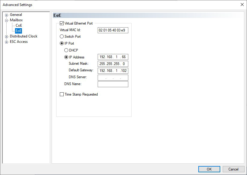
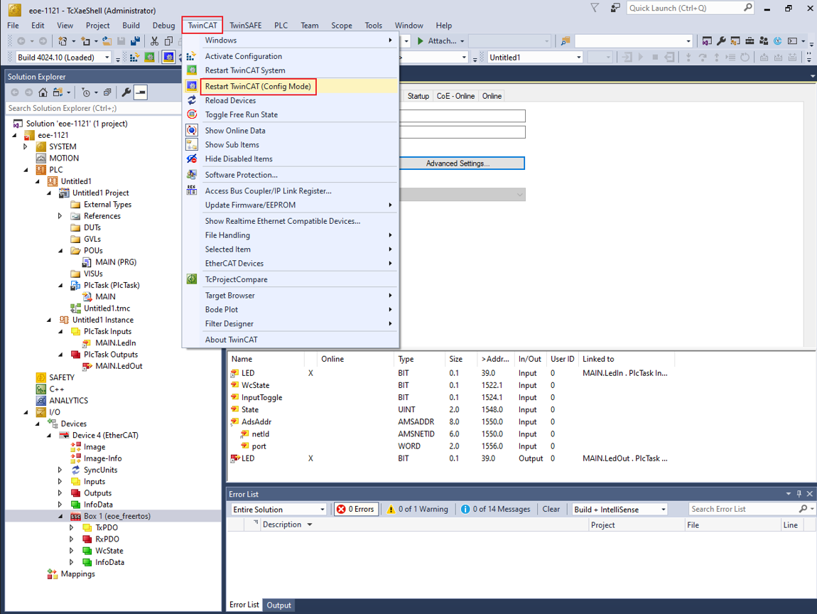
Activate the configuration.
To activate the configuration, select TwinCAT > Restart TwinCAT (Config Mode)..
After activaing the configuration, the serial port prints the following.
Start the SSC EoE example...
Hardware init success...
EoE interface init success...

***********************************************************
 HTTP Server example
***********************************************************
 IPv4 Address     : 192.168.1.66
 IPv4 Subnet mask : 255.255.255.0
 IPv4 Gateway     : 192.168.1.102
 mDNS hostname    : lwip-eoe
***********************************************************
Test ping and the http server.
Open cmd.exe and execute “ping 192.168.1.66”.
Make sure to disable the browser proxy and open the browser to access http://192.168.1.66.
Note: To modify the html of http server, refer tolwip_examples/lwip_httpsrv example.