Generate SB file for bootable image programming
To make the manufacturing process easier, all the commands supported by the flashloader and bootable image can be wrapped into a single SB file. Even if there are any changes in the application, MfgTool still uses this SB file to manufacture. The SB file can be updated separately without updating scripts for MfgTool use.
In this chapter, a bootable image will be created using the method in former chapter. Then corresponding SB file is generated using the bootable image. The BD file is prepared first to generate SB file for bootable image.
Generate SB file for FlexSPI NOR image programming
Generate Normal Bootable Image
For example, in RT1060, the FlexSPI NOR memory starts from address 0x6000_0000 and IVT from offset 0x1000. After following the steps in Section 4.2 (Generate unsigned normal i.MX RT bootable image) and BD file generation, here is the usage of the elftosb utility to create bootable image for FlexSPI NOR. All the BD files are provided in the release package. The figure below refers to the example command to generate a signed image.
Example command to generate signed FlexSPI boot image
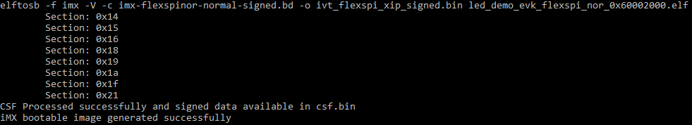
After running above command, a file with suffix “_nopadding.bin” is available into destination memory via subsequent SB file based on this binary.
Generate SB file for plaintext FlexSPI NOR image programming
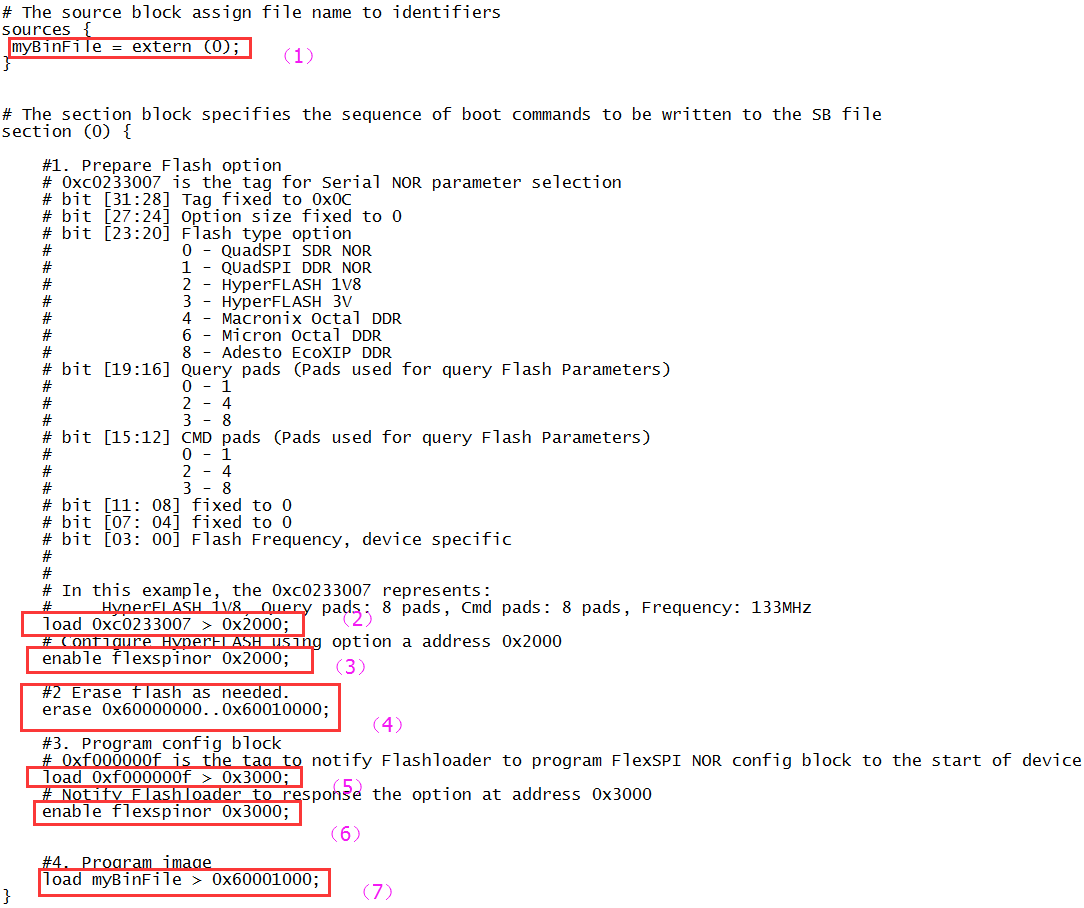
Usually, a BD file for FlexSPI NOR boot consists of 7 parts.
The bootable image file path is provided in sources block.
The FlexSPI NOR Configuration Option block is provided in section block.
To enable FlexSPI NOR access, the “enable” command must be used after the option block.
If the flash device is not erased, an “erase” command is required before programming data to the flash device. The erase operation is time consuming and is not required for a blank flash device (factory setting) during manufacturing.
The FlexSPI NOR Configuration Block (FNORCB) is required for FlexSPI NOR boot. To program the FNORCB generated by FlexSPI NOR Configuration Option block, a special magic number ‘0xF000000F” must be loaded into RAM first.
To notify the flashloader to program the FNORCB, an “enable” command must be used after the magic number is loaded.
After the above operation, the flashloader can program the bootable image binary into Serial NOR Flash through FlexSPI module using the load command.
An example containing the above steps is shown in the figure below.
Example BD file for FlexSPI NOR programming
Here is an example to generate SB file using the elftosb utility, ivt_flexspi_nor_xip.bin, and BD file shown in the figure below.
Example command to generate SB file for FlexSPI NOR programming
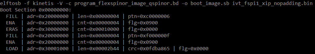
After the above command, a file named boot_image.sb will be created in the same folder that holds the elftosb utility executable.
Generate SB file for FlexSPI NOR Image encryption and programming
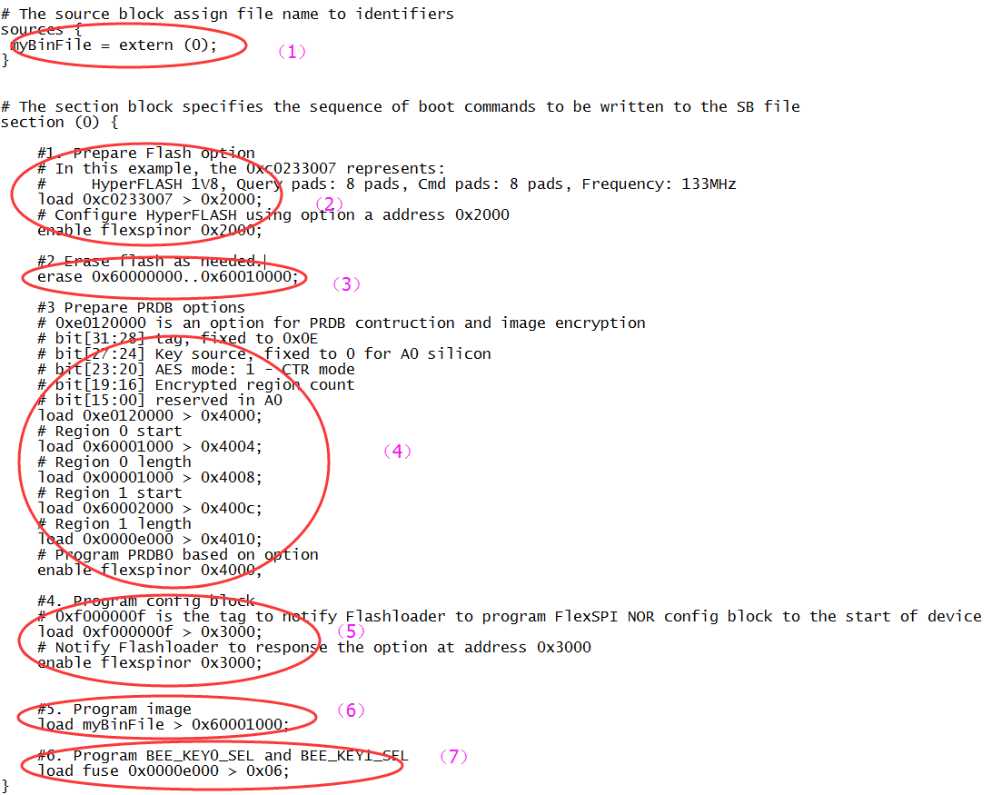
Usually, a BD file for FlexSPI NOR image encryption and programming consists of 7 steps.
The bootable image file path is provided in sources block.
Enable FlexSPI NOR access using FlexSPI NOR Configuration Option block.
Erase the flash device if it is not blank. The erase operation is time consuming and is not required for a blank flash device (factory setting) during manufacturing.
Enable image encryption using PRDB option block.
Program FNORCB using magic number.
Program boot image binary into Serial NOR via FlexSPI module.
Enable Encrypted XIP fuse bits.
Example BD file for encrypted FlexSPI NOR image generation and programming
The steps to generate SB file is the same as in the above section.
Generate SB file for FlexSPI NAND image programming
For FlexSPI NAND boot, the IVT offset is always 0x400. However, to reduce effort in calculating the start address for each firmware region, the Flashloader supports programming the FlexSPI NAND boot image to corresponding firmware region in block granularity. So, the bootable image without “_nopadding” suffix will be used.
Generate SB file for FlexSPI NAND image programming
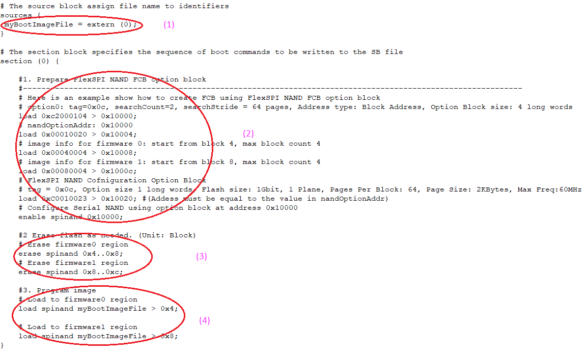
In general, a BD file for FlexSPI NAND image programming consists of 4 steps.
The bootable image file path is provided in sources block.
Enable FlexSPI NAND access using FlexSPI NAND Configuration Option block.
Erase SPI NAND device as needed.
Program boot image binary into Serial NAND via FlexSPI module.
Example BD file for FlexSPI NAND image programming
Generate SB file for encrypted FlexSPI NAND Image and KeyBlob programming
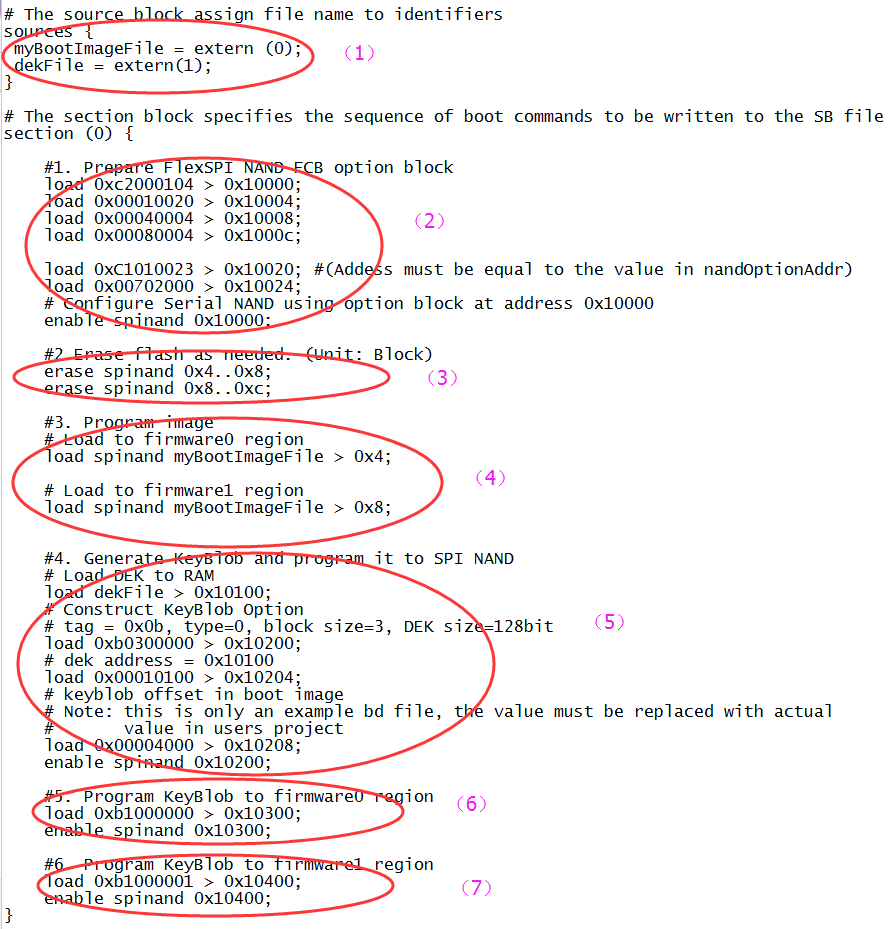
Generally, the BD file for FlexSPI NAND image programming with KeyBlob consists of 7 steps.
The bootable image file path is provided in sources block.
Enable FlexSPI NAND access using FlexSPI NAND Configuration Option block.
Erase SPI NAND device as needed.
Program boot image binary into Serial NAND via FlexSPI module.
Update KeyBlob information using KeyBlob Option block.
Program KeyBlob block into SPI NAND for firmware 0.
Program KeyBlob block into SPI NAND for firmware 1.
An example BD file is shown in the figure below.
Example BD file for encrypted FlexSPI NAND image and KeyBlob programming
Generate SB file for SD image programming
The SD image always starts at offset 0x400. The i.MX RT boot image generated by the elftosb utility with “_nopadding.bin” will be used for programming.
Steps to Generate SB file for SD image programming
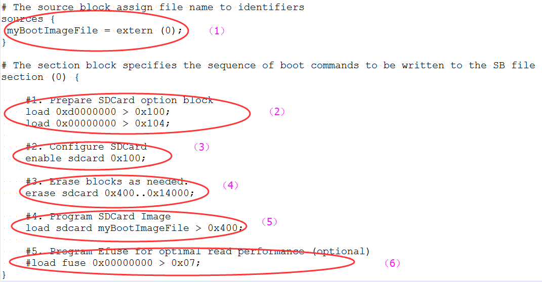
In general, there are six steps in the BD file to program the bootable image to SD card.
The bootable image file path is provided in sources block.
Prepare SDCard option block.
Enable SDCard access using enable command.
Erase SD card memory as needed.
Program boot image binary into SD card.
Program optimal SD boot parameters into Fuse (optional, remove it if it is not required in actual project).
An example is shown in the figure below.
Example BD file for SD boot image programming
The steps to generate SB file for encrypted SD boot image and KeyBlob programming is similar to FlexSPI NAND. See the example below for more details.
# The source block assign file name to identifiers
            sources {
            myBootImageFile = extern (0);
            dekFile = extern (1);
            }
            # The section block specifies the sequence of boot commands to be written to the SB file
            section (0) {
            #1. Prepare SDCard option block
            load 0xd0000000 > 0x100;
            load 0x00000000 > 0x104;
            #2. Configure SDCard
            enable sdcard 0x100;
            #3. Erase blocks as needed.
            erase sdcard 0x400..0x14000;
            #4. Program SDCard Image
            load sdcard myBootImageFile > 0x400;
            #5. Generate KeyBlob and program it to SD Card
            # Load DEK to RAM
            load dekFile > 0x10100;
            # Construct KeyBlob Option
            #---------------------------------------------------------------------------
            # bit [31:28] tag, fixed to 0x0b
            # bit [27:24] type, 0 - Update KeyBlob context, 1 Program Keyblob to SPI NAND
            # bit [23:20] keyblob option block size, must equal to 3 if type =0,
            #             reserved if type = 1
            # bit [19:08] Reserved
            # bit [07:04] DEK size, 0-128bit 1-192bit 2-256 bit, only applicable if type=0
            # bit [03:00] Firmware Index, only applicable if type = 1
            # if type = 0, next words indicate the address that holds dek
            #              the 3rd word
            #----------------------------------------------------------------------------
            # tag = 0x0b, type=0, block size=3, DEK size=128bit
            load 0xb0300000 > 0x10200;
            # dek address = 0x10100
            load 0x00010100 > 0x10204;
            # keyblob offset in boot image
            # Note: this is only an example bd file, the value must be replaced with actual
            #       value in users project
            load 0x00004000 > 0x10208;
            enable sdcard 0x10200;
            #6. Program KeyBlob to firmware0 region
            load 0xb1000000 > 0x10300;
            enable sdcard 0x10300;
            #7. Program Efuse for optimal read performance (optional)
            #load fuse 0x00000000 > 0x07;
            }
Generate SB file for eMMC image programming
The eMMC image always starts at offset 0x400. The i.MX RT boot image generated by the elftosb utility with “_nopadding.bin” will be used for programming.
There are two types of eMMC boot mode: Normal boot and Fast boot
Normal mode
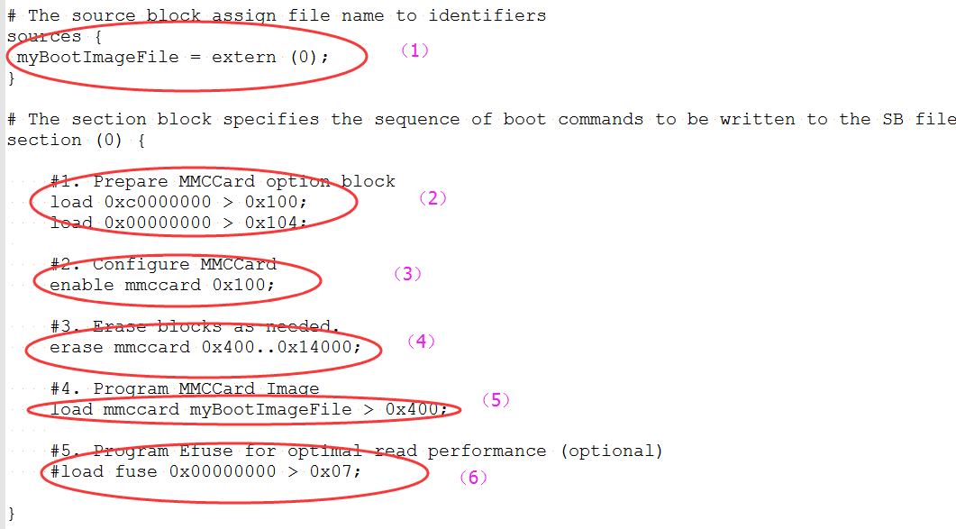
There are 6 steps in the BD file to program the bootable image to eMMC for normal boot mode.
The bootable image file path is provided in sources block.
Prepare eMMC option block.
Enable eMMC access using enable command.
Erase eMMC card memory as needed.
Program boot image binary into eMMC.
Program optimal eMMC boot parameters into Fuse (optional, remove it if it is not required in actual project).
Example BD file for eMMC boot image programming for Normal boot mode
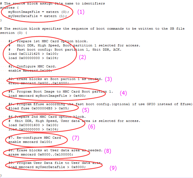
Fast Mode
There are nine steps in the BD file to program the bootable image to eMMC for Fast boot mode.
The bootable image file path is provided in “sources” block.
Prepare eMMC option block and enable eMMC access using “enable” command.
Erase eMMC card memory as needed.
Program boot image binary into eMMC.
Program optimal eMMC boot parameters into Fuse (optional, remove it if it is not required in actual project).
Prepare 2nd eMMC option block.
Re-enable eMMC access using new option block.
Erase data in User Data area as required.
Load User Data file to User Data area.
Example BD file for eMMC boot image programming for Fast boot mode
The BD file for encrypted eMMC boot image and KeyBlob programming is similar to SD.
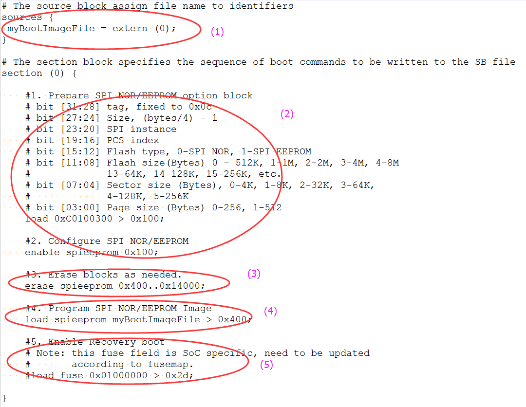
Generate SB file for Serial NOR/EEPROM image programming
There are five steps in the BD file to program the bootable image to SD card.
The bootable image file path is provided in sources block.
Prepare Serial NOR/EEPROM option block and enable Serial NOR/EEPROM access using enable command.
Erase Serial NOR/EEPROM memory as required.
Program boot image binary into Serial NOR/EEPROM device.
Enable Recovery Boot via Serial NOR/EEPROM as required.
An example is shown in the figure below.
Example BD file for Serial NOR/EEPROM boot image programming
The BD file for encrypted SPI EEPRM/NOR boot image and KeyBlob programming is similar to SD.
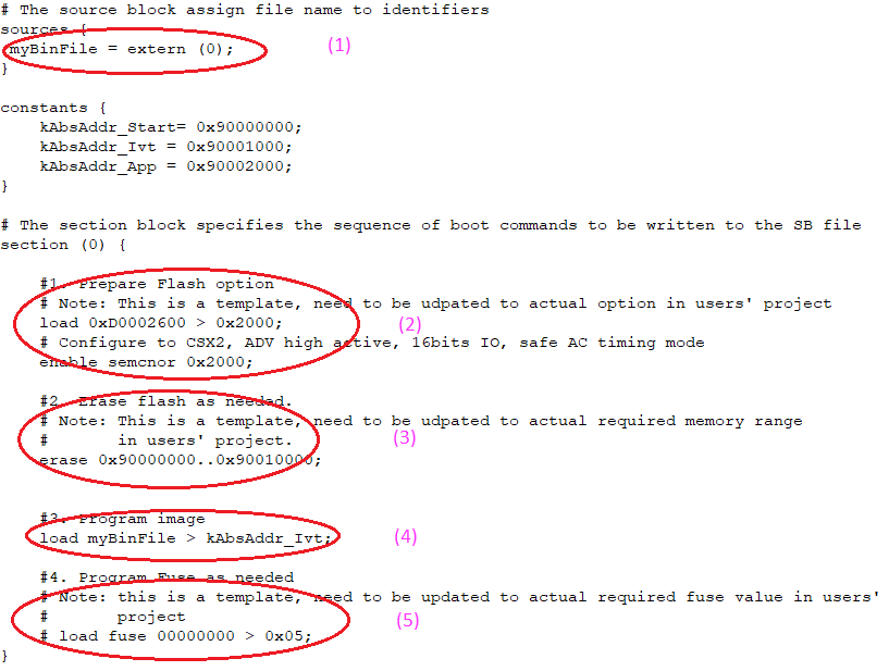
Generate SB file for SEMC NOR image programming
In general, there are 5 steps in the BD file to program the bootable image to SD card.
The bootable image file path is provided in sources block.
Prepare SEMC NOR option block and SEMC NOR access using enable command.
Erase SEMC NOR memory as required.
Program boot image binary into SEMC NOR device.
Program optimal SEMC NOR access parameters to Fuse as required.
An example BD file is shown in the figure below.
Example BD file for SEMC NOR boot image programming
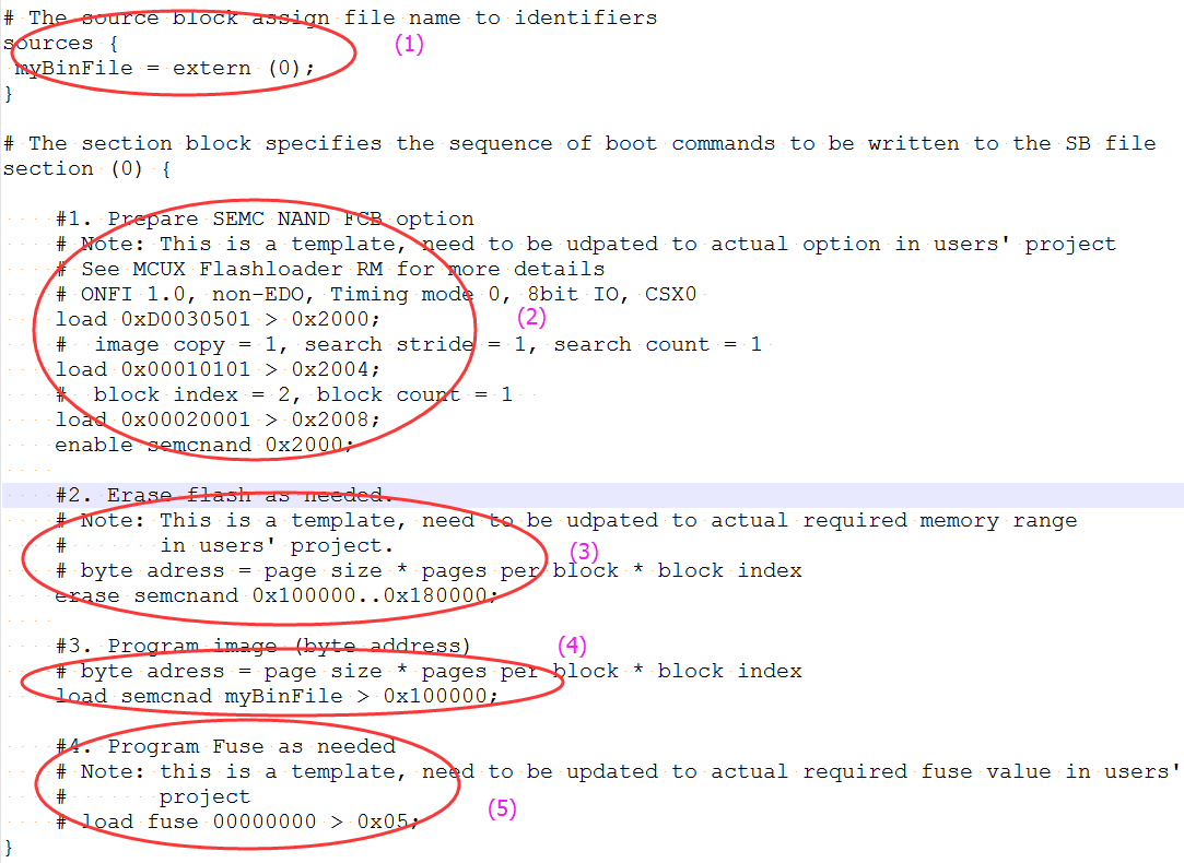
Generate SB file for SEMC NAND image programming
There are 5 steps in the BD file to program the bootable image to SD card.
The bootable image file path is provided in sources block.
Prepare SEMC NAND FCB option block and SEMC NAND access using enable command.
Erase SEMC NAND memory as required.
Program boot image binary into SEMC NAND device.
Program optimal SEMC NAND access parameters to Fuse as required.
An example is shown in the figure below.
Example BD file for SEMC NAND boot image programming
Generate SB file for fuse programming
In certain cases, the fuse must be programmed first to enable specific features for selected boot devices or security levels. For example, to enable Fast boot mode for eMMC, enable HAB closed mode, the fuse must be programmed first.
The elftosb utility can support programming the fuses using the built-in command load fuse. An example to program SRK table and enable HAB closed mode is shown as follows.
# The source block assign file name to identifiers
sources {
}
constants {
}
section (0) {
    # Program SRK table
    load fuse 0xD132E7F1 > 0x18;
    load fuse 0x63CD795E > 0x19;
    load fuse 0x8FF38102 > 0x1A;
    load fuse 0x22A78E77 > 0x1B;
    load fuse 0x01019c82 > 0x1C;
    load fuse 0xFC3AC699 > 0x1D;
    load fuse 0xF2C327A3 > 0x1E;
    load fuse 0xDAC9214E > 0x1F;
    # Program SEC_CONFIG to enable HAB closed mode
    load fuse 0x00000002 > 0x06;
}