Appendix#
Example of manufacturing flow for RT1160-EVK#
Manufacturing process in Development phase#
In development phase, generally the image is unsigned and is used for functional testing.
Templates options for the Manufacturing flow#
To simplify the complexity of the Manufacturing flow, several templates are available in ucl2.xml.
The code block below is an example which is used for programming an SDK XIP project binary into RT1160-EVK board. To enable the XiP users need to
Change the “name” item in cfg.ini to “name = MXRT116x-DevBootFlexSpi1_FlashXiP
Compile the SDK project
Generate the binary file for the project
Rename the binary to boot_image.bin
Copy it to the same folder as ucl2.xml
<!-- This List is for the MCUXpresso SDK XIP demo download via the MfgTool -->
        <LIST name="MXRT116x-DevBootFlexSpi1_FlashXiP" desc="Manufacturing with Flashloader">
        <!-- Stage 1, load and execute Flashloader -->
        <CMD state="Blhost" type="blhost" body="load-image \"Profiles\\MXRT116x\\OS Firmware\\ivt_flashloader.bin"> Loading and running Flashloader. </CMD>
        <!-- Stage 2, Program boot image into external memory using Flashloader -->
        <CMD state="Blhost" type="blhost" body="get-property 12" > Get Property 12. </CMD> <!--Used to test if flashloader runs successfully-->
        <CMD state="Blhost" type="blhost" body="fill-memory 0x20000000 4 0xcf900001"> Select Instance : 1</CMD>
        <CMD state="Blhost" type="blhost" body="configure-memory 0x9 0x20000000"> Enable the FLEXSPI 1 support </CMD>
        <!--Note: This configuration is just an example, please use the correct option for the flash device soldered on the platorm
        See the usage of the configuration option from the System Boot, FLEXSPI NOR API section
        -->
        <CMD state="Blhost" type="blhost" body="fill-memory 0x20000000 4 0xc0000006> Prepare Flash Configuration option </CMD>
        <CMD state="Blhost" type="blhost" body="configure-memory 0x9 0x20000000"> Configure QuadSPI NOR Flash </CMD>
        <!-- This erase size need to be updated based on the actual boot image size-->
        <CMD state="Blhost" type="blhost" timeout="30000" body="flash-erase-region 0x30000000 0x100000" > Erase 1MBytes </CMD>
        <CMD state="Blhost" type="blhost" timeout="15000" body="write-memory 0x30000400 \"Profiles\\MXRT116x\\OS Firmware\\boot_image.bin\"" > Program Boot Image. </CMD>
        <CMD state="Blhost" type="blhost" body="Update Completed!">Done</CMD>
        </LIST>
The code block below is an example which is used for programming the SDK XIP project binary into RT1160-EVK board with other FLASH device. Users may need to modify the **** configuration option for actual soldered FLASH devices. See chapter “External memory support” in MCU Flashloader Reference Manual for more details.
To enable the option, users need to
Change the “name” item in cfg.ini to MXRT116x-DevBootFlexSpi1_FlashXiP_NoConfigBlock”
Compile the SDK project
Generate the binary file for the project
Rename the binary to boot_image.bin
Copy it to the same folder as ucl2.xml
<!-- This List is for the MCUXpresso SDK XIP demo download via the MfgTool -->
            <LIST name="MXRT116x-DevBootFlexSpi1_FlashXiP_NoConfigBlock" desc="Manufacturing with Flashloader">
            <!-- Stage 1, load and execute Flashloader -->
            <CMD state="Blhost" type="blhost" body="load-image \"Profiles\\MXRT116x\\OS Firmware\\ivt_flashloader.bin"> Loading and running Flashloader. </CMD>
            <!-- Stage 2, Program boot image into external memory using Flashloader -->
            <CMD state="Blhost" type="blhost" body="get-property 12" > Get Property 12. </CMD> <!--Used to test if flashloader runs successfully-->
            <CMD state="Blhost" type="blhost" body="fill-memory 0x20000000 4 0xcf900001"> Select Instance : 1</CMD>
            <CMD state="Blhost" type="blhost" body="configure-memory 0x9 0x20000000"> Enable the FLEXSPI 1 support </CMD>
            <!--Note: This configuration is just an example, please use the correct option for the flash device soldered on the platorm
            See the usage of the configuration option from the System Boot, FLEXSPI NOR API section
            -->
            <CMD state="Blhost" type="blhost" body="fill-memory 0x20000000 4 0xc0000006"> Prepare Flash Configuration option </CMD>
            <CMD state="Blhost" type="blhost" body="configure-memory 0x9 0x20000000"> Configure QuadSPI NOR Flash </CMD>
            <!-- This erase size need to be updated based on the actual boot image size-->
            <CMD state="Blhost" type="blhost" timeout="30000" body="flash-erase-region 0x30000000 0x100000" > Erase 1MBytes </CMD>
            <!-- Program the Flash Config block to the FLASH ofset 0x400 automatically -->
            <CMD state="Blhost" type="blhost" body="fill-memory 0x20000000 4 0xf000000f"> Prepare Flash Configuration option </CMD>
            <CMD state="Blhost" type="blhost" body="configure-memory 0x9 0x20000000"> Configure QuadSPI NOR Flash </CMD>
            <CMD state="Blhost" type="blhost" timeout="15000" body="write-memory 0x30000400 \"Profiles\\MXRT116x\\OS Firmware\\boot_image.bin\"" > Program Boot Image. </CMD>
            <CMD state="Blhost" type="blhost" body="Update Completed!">Done</CMD>
            </LIST>
Create i.MX RT bootable image#
Create image using KSDK XIP example#
Users can create an unsigned bootable image by building a KSDK XIP project and convert the output to a binary file. The binary file needs to be renamed to the boot_image.bin and copied to the same folder as ucl2.xml. Then users can update the cfg.ini file to enable an option of manufacturing flow which is described in previous section.
Create image using the elftosb utility#
To create a bootable image for a specific memory, users need to know the memory map of i.MX RT116x SoC. Details of generating bootable image can be found in Chapter 4. Here are the steps to create an i.MX RT bootable image for FlexSPI NOR using elftosb utility.
Create the BD file for boot image generation. The BD file content is showed below. It is also available in the release package in “<sdk_package>/middleware/mcu-boot/bin/Tools/bd_file/imxrt116xfolder
options {
    flags = 0x00;
    startAddress = 0x30000000;
    ivtOffset = 0x1000;
    initialLoadSize = 0x2000;
}
                entryPointAddress = 0x30002000;
sources {
    elfFile = extern(0);
}
section (0)
{
}
Create the i.MX RT bootable image using elftosb utility.
Here is the example command:
Example command to generate FlexSPI NOR boot image

ivt_flexspi_nor_xip.bin
ivt_flexspi_nor_xip_nopadding.bin
The ivt_flexspi_nor_xip_nopadding.bin will be used to generate SB file for QSPI FLASH programming in subsequent section.
Create SB file for QSPI FLASH programming#
Here is an example to create an SB file for QSPI FLASH programming for RT1160-EVK board. The details for generating SB file for bootable image programming is available in Chapter 5.
# The source block assign file name to identifiers
sources {
 myBinFile = extern (0);
}
constants {
kAbsAddr_Start= 0x30000000;
                kAbsAddr_Ivt = 0x30001000;
                kAbsAddr_App = 0x30002000;
}
# The section block specifies the sequence of boot commands to
# be written to the SB file
section (0) {
    #1. Prepare Flash option
    # 0xc0000007 is the tag for Serial NOR parameter selection
    # bit [31:28] Tag fixed to 0x0C
    # bit [27:24] Option size fixed to 0
    # bit [23:20] Flash type option
    #             0 - QuadSPI SDR NOR
    #             1 - QUadSPI DDR NOR
    # bit [19:16] Query pads (Pads used for query Flash Parameters)
    #             0 - 1
    # bit [15:12] CMD pads (Pads used for query Flash Parameters)
    #             0 - 1
    # bit [11: 08] Quad Mode Entry Setting
    #             0 - Not Configured, apply to devices:
    #                 - With Quad Mode enabled by default or
    #                 - Compliant with JESD216A/B or later revision
    #             1 - Set bit 6 in Status Register 1
    #             2 - Set bit 1 in Status Register 2
    #             3 - Set bit 7 in Status Register 2
    #             4 - Set bit 1 in Status Register 2 by 0x31 command
    # bit [07: 04]  Misc. control field
    #             3 - Data Order swapped, used for Macronix OctaFLASH devcies only
    #             (except MX25UM51345G)
    #             4 - Second QSPI NOR Pinmux
    # bit [03: 00] Flash Frequency, device specific
    load 0xc0000006 > 0x2000;
    # Configure QSPI NOR FLASH using option a address 0x2000
    enable flexspinor 0x2000;
    #2 Erase flash as needed.
    #(Here only 64KBytes are erased, need to be adjusted to the actual
    #size of users' application)
    erase 0x 30000000..0x30040000
                ;
    #3. Program config block
    # 0xf000000f is the tag to notify Flashloader to program
    # FlexSPI NOR config block to the start of device
    load 0xf000000f > 0x3000;
    # Notify Flashloader to response the option at address 0x3000
    enable flexspinor 0x3000;
    #4. Program image
    load myBinFile > kAbsAddr_Ivt;
}
After the BD file is ready, the next step is to generate the boot_image.sb file that is for MfgTool to use later. Here is the example command:
Example command to generate SB file for FlexSPI NOR programming
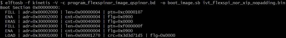
After using the above command, the boot_image.sb is generated in the elftosb utility folder.
Program Unsigned Image to Flash using MfgTool#
Use the following steps to program a boot image into a flash device
Copy the boot_image.sb file to “<mfgtool_root_dir>/Profiles/MRT116x/OS Firmware” folder.
Change the “name” under “[List]” to selected option in cfg.ini file in <mfgtool_root_dir> folder, for example, “name = MXRT116x-DevBootFlexSpi1_FlashXiP”.
Put the -EVK board to Serial Downloader mode by setting SW1 to “1-OFF, 2-OFF, 3-OFF, 4-ON”.
Power up RT1160-EVK board and insert USB cable to J20.
Open MfgTool, it will show as the detected device like the one shown in Connect to the i.MX RT Platform.
Click “Start”, MfgTool will do manufacturing process. After completion, it will show the status as success as shown in Program bootable image during development. Click “Stop” and close the MfgTool.
Put the RT1160-EVK board to internal boot mode and select QSPI FLASH as boot device by setting SW1 to “1-OFF, 2-OFF,3-ON, 4-OFF”. Then reset the device to start running the application