Demo setup#
The usb_pd demo is described in this section. For information about usb_pd_battery, usb_pd_source_charger, and usb_pd_alt_mode_dp_host, see the readme file in the corresponding demos’ directory.
The LPCXpresso54114 and USB-PD/Type C shield board om13588 is used as the example.
In this demo, several functionalities are demonstrated: Power Role Swap, Request 5 V or higher voltage, Hard Reset, and so on. There are two ways to control the demo, using the button or user menu. Due to the limitation of number of hardware buttons, additional functionalities are provided via user menu. The follow table indicates the way it is used on different boards:
||Power request software|Power change software| |::|:——————–:|:——————-:| |FRDM-K22F|SW2|SW3| |FRDM-K64F|SW2|SW3| |FRDM-KL27Z|SW1|SW3| |FRDM-KL28Z|user menu|user menu| |FRDM-KL32L2A4S|user menu|user menu| |IMXRT1050-EVKB|user menu|user menu| |LPCXpresso54018|SW4|SW5| |LPCXpresso54114|SW1|SW2| |LPCXpresso54608|SW4|SW5| |LPCXpresso55S16|user menu|user menu| |LPCXpresso55S28|user menu|user menu| |LPCXpresso55S69|user menu|user menu| |MIMXRT685-EVK|user menu|user menu| |MIMXRT1015-EVK|user menu|user menu| |MIMXRT1020-EVK|user menu|user menu| |MIMXRT1050-EVK|user menu|user menu| |MIMXRT1060-EVK|user menu|user menu| |MIMXRT1064-EVK|user menu|user menu| |MC56F83000-EVK|user menu|user menu| |MIMXRT1170-EVK|user menu|user menu| |MIMXRT1060-EVKB|user menu|user menu| |MIMXRT1160-EVK|user menu|user menu| |MIMXRT595-EVK|user menu|user menu| |LPCXpresso55S36|user menu|user menu| |MIMXRT685-AUD-EVK|user menu|user menu|
Note: For some boards there are no switches to use. So, this demo uses menus to implement the same functionality as a switch. The menus correspond to the switches as follows and can be obtained by inputting 0 in the debug console.
|Switch|Menu item| |Short press Power request switch|Request 5 V| |Long press Power request switch|Request high voltage| |Short press Power change switch|Power role swap| |Long press Power change switch|Hard reset|
Note: The VBus test point is J5 of the USB-PD/Type C Shield board.
Setup hardware boards#
Connect the debug console port to PC. For example, connect J7 of LPCXpresso54114 to the PC.
Set the shield board’s jumpers and connect the shield board with the development board as shown in section Hardware re-work.
Connect a 9 V power source to the J1 jack in the USB-PD/Type C Shield board. The shield LEDs status is as follows:
|
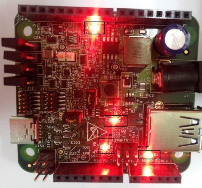
|
Ensure you run the usb_pd demo by using the instructions in section Running the demo.
“pd init success” prints in the debug console.
Parent topic:Demo setup
Request from original sink role#
Connect a USB Type-C cable between two boards. One works as a sink and one works as a source. You can see it through the debug console.
Connect a voltmeter to VBus (J5) of the sink role board. The voltmeter at the sink role shows approximately 5 V.
|
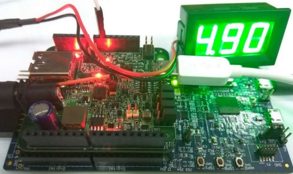
|
Press “Power request switch ” for about 3 seconds to make 9 V request. After the request is completed successfully, the voltmeter shall show 9 V.
|
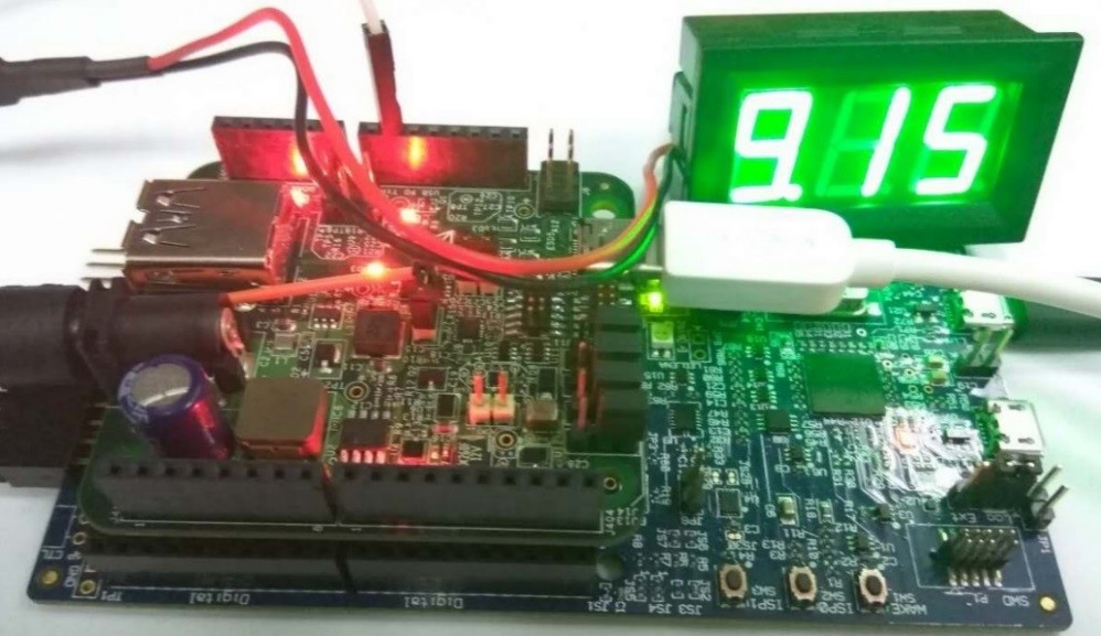
|
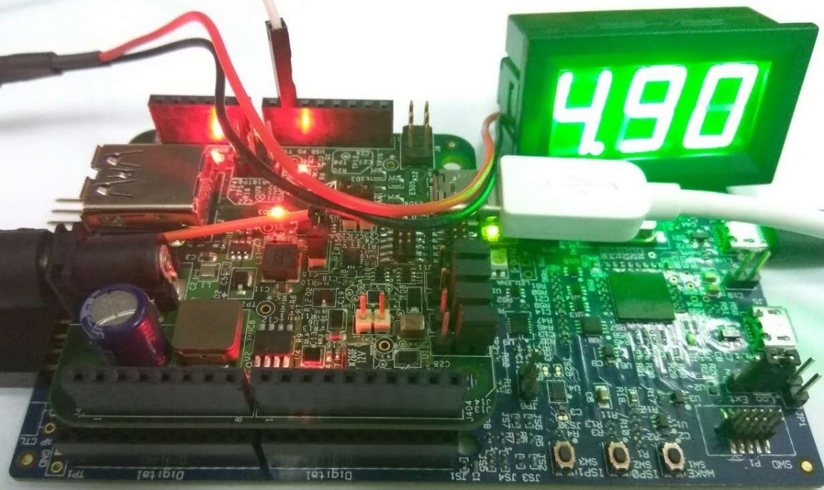
Immediately press “Power request switch” to make 5 V request. After the request is completed successfully, the voltmeter shows approximately 5 V.
|

|
Parent topic:Demo setup
Power swap from sink role#
Immediately press the “Power change switch” on the sink to make PR_SWAP.
The voltage of the VBus drops to 0 V, then back to 5 V.
Parent topic:Demo setup
Request from original source role#
Connect a voltmeter to VBus (J5) of the new sink role board. After the power role swap, the original source role becomes the sink role. The voltmeter at the source role shows approximately 5 V.
|

|
Press the “Power request switch ” for about 3 seconds to make 9 V request. After the request is completed successfully, the voltmeter shows approximately 9 V.
|

|
Immediately press the “Power request switch ” to make 5 V request. After the request is completed successfully, the voltmeter shows approximately 5 V.
|
|
Parent topic:Demo setup
Power swap from source role#
Immediately press “power change switch ” on the source to make PR_SWAP.
The voltage of the VBus drops to 0 V, then back to 5 V.
Parent topic:Demo setup
Hard reset test#
Press the “Power change switch ” for 3 seconds to make HARD_RESET.
The Voltage of the VBus drops to 0 V, then back to 5 V.
The source and sink state machine restart, and sink requests the power again. This can be seen in the logs in the debug console.
Parent topic:Demo setup
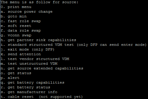
Test other commands#
Input ‘0’ in the debug console. The following menu is printed in the debug console (the menu is a little different for source and sink):
|
|
Input the menu to test the corresponding command.
For example, if you input ‘f’, the “data role swap” command begins, and the debug console prints the result.
Parent topic:Demo setup