Over the Air Programming (OTAP)
This section describes the implemented profiles and services, user interactions, and testing methods for the Bluetooth LE OTAP application.
Implemented profile and services
The Bluetooth LE OTAP applications implement the GATT client and server for the custom Bluetooth LE OTAP profile and service.
Bluetooth LE OTAP Service (UUID: 01ff5550-ba5e-f4ee-5ca1-eb1e5e4b1ce0)
The Bluetooth LE OTAP Service is a custom service which has 2 characteristics.
OTAP Control Point Characteristic (UUID: 01ff5551-ba5e-f4ee-5ca1-eb1e5e4b1ce0). This characteristic can be written and indicated to exchange OTAP Commands between the OTAP Server and the OTAP Client. Data chunks are not transferred using this characteristic.
OTAP Data Characteristic(UUID: 01ff5552-ba5e-f4ee-5ca1-eb1e5e4b1ce0). This characteristic can be written without response by the OTAP Server to transfer image file data chunks to the OTAP Client only when an image block transfer is requested via the ATT transfer method. Data chunks can also be transferred via the L2CAP credit-based PSM channels method.
The demo runs using 3 applications: an OTAP Client embedded application, an OTAP Server embedded application, and an Over the Air Programming PC application. The OTAP Client embedded application has two versions, an ATT version and a L2CAP version each using a different transfer method.
The embedded OTAP Server application is a GAP Central application which scans for devices advertising the Bluetooth LE OTAP service. After it finds one, it connects to it and configures the OTAP Control Point CCC Descriptor to receive ATT Indications from the device then it waits for OTAP commands from this device.
Once commands start arriving from the OTAP Client via ATT Indications the OTAP Server relays them via serial interface to a PC application which responds. The responses are then sent back to the OTAP Client by writing the OTAP Control Point Characteristic. The embedded OTAP Server application effectively acts as a relay between the OTAP Client to which the image is sent over the air and the Over the Air Programming PC application which has an OTAP image file constructed using a binary ‘.srec’ image or a ‘.bin’ image.
The OTAP Client is a GAP Peripheral which advertises the Bluetooth LE OTAP Service and waits for a connection from an OTAP Server. After an OTAP Server connects, the OTAP Client waits for it to write the OTAP Control Point CCCD and then starts sending commands via ATT Indications. If the OTAP Client is configured to ask the data transfer via the L2CAP CoC PSM, it registers and tries to connect a predetermined L2CAP PSM before sending any commands to the OTAP Server.
Parent topic:Over the Air Programming (OTAP)
Supported platforms
The following platforms support the OTAP applications:
KW45B41Z-EVK
K32W148-EVK
FRDM-MCXW71
KW47-EVK
MCXW72-EVK
FRDM-MCXW72
Parent topic:Over the Air Programming (OTAP)
User interface
After flashing two boards with the OTAP Server and OTAP Client applications respectively, the devices are in Idle mode (all LEDs flashing). To start advertising, press the ADVSW button on the OTAP Client. To start scanning, press the SCANSW button on the OTAP Server. After the two devices connect and start exchanging commands. CONNLED becomes solid on the OTAP Server and on the OTAP Client.
Start the OTAP Server PC application after the embedded applications are flashed to the boards. The application creates an OTAP image file using the provided executable .srec or .bin file. It then connects to the embedded OTAP Server via the configured serial interface and waits for commands. The application shows details about the image file creation and allows the OTAP upgrade image file header to be configured. The log view of the application displays the interactions between the OTAP Client and the OTAP Server.
See Table 1 for the hardware references.
Platform |
ADVSW |
SCANSW |
CONNLED |
|---|---|---|---|
KW45B41Z-EVK / K32W148-EVK |
SW2 |
SW2 |
LED2 |
FRDM-MCXW71 |
SW2 |
SW2 |
Blue LED |
KW47-EVK / MCXW72-EVK |
SW2 |
SW2 |
LED2 |
FRDM-MCXW72 |
SW4 |
SW4 |
Blue LED |
Parent topic:Over the Air Programming (OTAP)
Usage with Over The Air Programming Tool
Below is a list of requirements for usage with Test Tool for Connectivity products:
Over The Air Programming Tool 1.4.0 or newer on CONNECTIVITY-TOOL-SUITE
Serial COM port drivers – these are board-specific.
To run the application, follow the steps below:
Flash the OTAP Server onto a supported platform and the OTAP Client to another supported platform. Make sure the board running the OTAP Server is connected to your PC and your PC has appropriate drivers for the USB to serial device on that board.
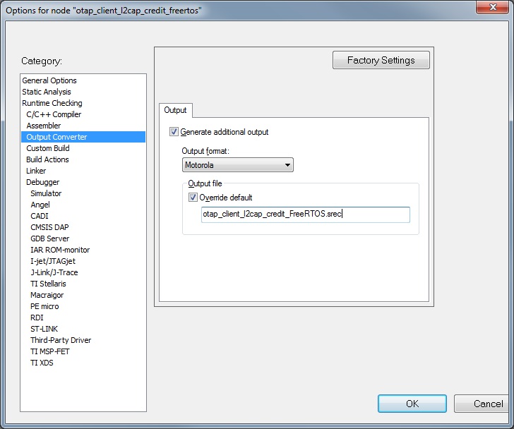
Create the application to send over the air. The executable must be provided in the
.srecor.binformat. The.srecformat executable can be obtained by using the IAR Output Converter and setting the output format to Motorola as shown in in the figure below.When compiling an image for the Over-the-Air update, the
gEraseNVMLink_dlinker symbol must be set to0andgUseSecureBoot_dset to1only if you are using external storage support.In a specific use case, external storage support might be used and the image is created in MCUXpresso IDE. If this image is close to the maximum size of the internal storage, then a new flash section must be added before the NVM section. This step is necessary to ensure that the signature data does not overlap the NVM section. The flash section should be significant enough to accommodate the signature data.
To obtain a
.binfile from IAR, select the Raw binary option in the IAR Output Converter as seen in the in the figure below.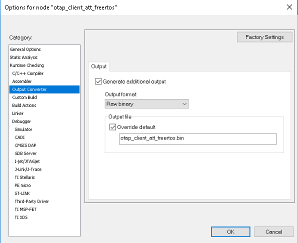
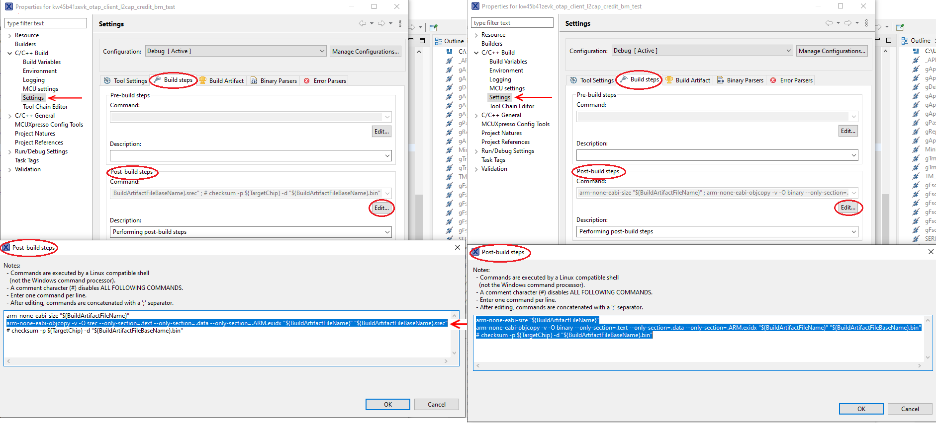
To obtain a
.binfile from MCUXpresso IDE, go to the Project properties -> Settings -> Build stepswindow and press the Editbutton for the Post-build steps. A Post-build steps window shows up. In this window, add the following command:arm-none-eabi-objcopy -v -O binary --only-section=.text --only-section=.data --only-section=.ARM.exidx "${BuildArtifactFileName}" "${BuildArtifactFileBaseName}.bin"
In case the command already exists, uncomment it by removing the ‘#’ character at the beginning.
To obtain a
.srec (.s19)file, add or uncomment the following post-build command in the same window:arm-none-eabi-objcopy -v -O srec --only-section=.text --only-section=.data --only-section=.ARM.exidx" ${BuildArtifactFileName}" "${BuildArtifactFileBaseName}.s19"This window is shown in the figure below.
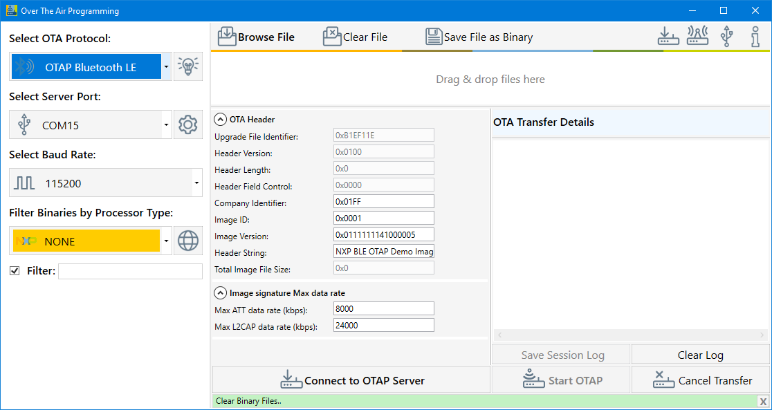
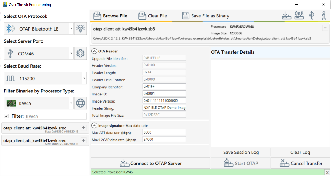
Start the Over The Air Programming application and select “OTAP Bluetooth LE” from the “Select OTA Protocol” combo box as shown in the figure below.
Load the image file into the application, then configure the image file header and start the OTAP Server:
To select the updated image In the Over the Air Programming tool, select the “Browse File” button and then navigate to the
.srecor.binfile containing the image to be sent to the OTAP Client. After the.srecor.binfile is chosen, a pop-up window asks to choose the target processor. Choose the KW45/K32W processor and press OK. See the figure below.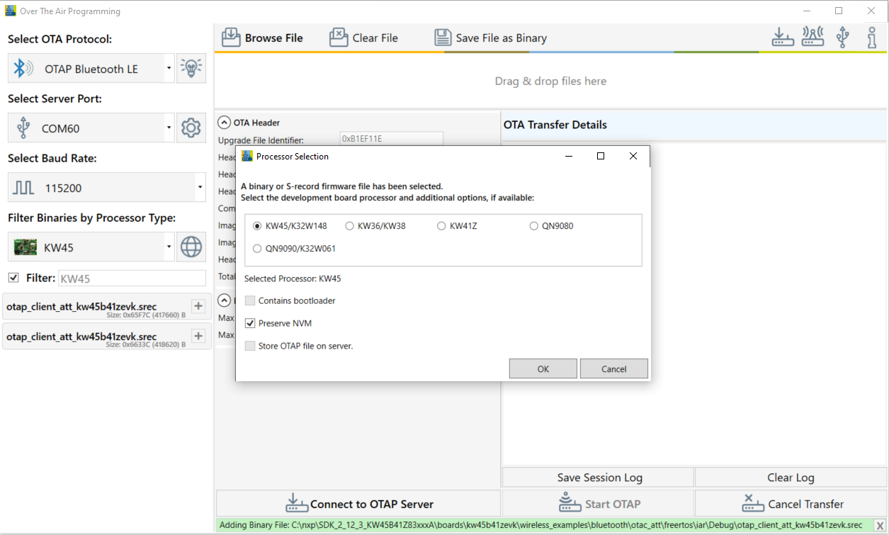
Once the processor is selected, a new pop-up window would appear that allows selecting the type of image (KW45Z/K32W1(MCU)) as shown in the figure below.
(In the specified case, we selected the KW45Z/KW45Z/K32W1(MCU).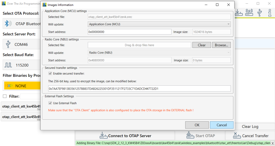
To update the KW45B/KW32W1 (radio) image, select it by pressing the “Browse” button in the M3 group. Then navigate to the
.binfile as shown in the figure below.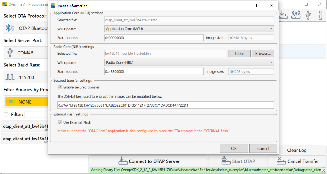
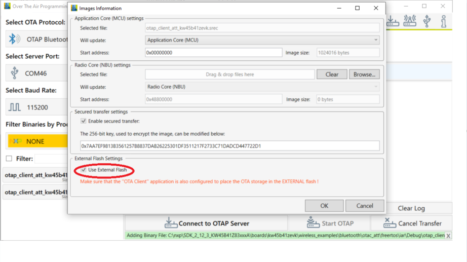
If the OTA client has configured external memory support, then “Use External Flash” checkbox must be checked as in the figure below. If the OTA client has configured internal memory support, the checkbox must be left unchecked.
This checkbox (if checked) instructs the OTA client bootloader to erase all the internal storage. This must be done only if external memory support is used as shown in the figure below.
.
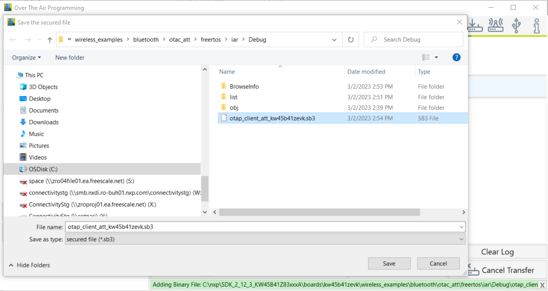
At this moment, click the OKbutton. A new window appears that prompts you to enter a location where the secured file should be stored. By default, the location of the original file is selected. See the figure below.
Note: The extension of the secured file is *.sb3. See the figure below.
You can now configure two different JSON files, used to:
Sign the file that is uploaded to the MCU if an MCU file was selected.
Create the *.sb3container that is sent OTA. The *.sb3 file can contain only the MCU file, only the radio file, or both.
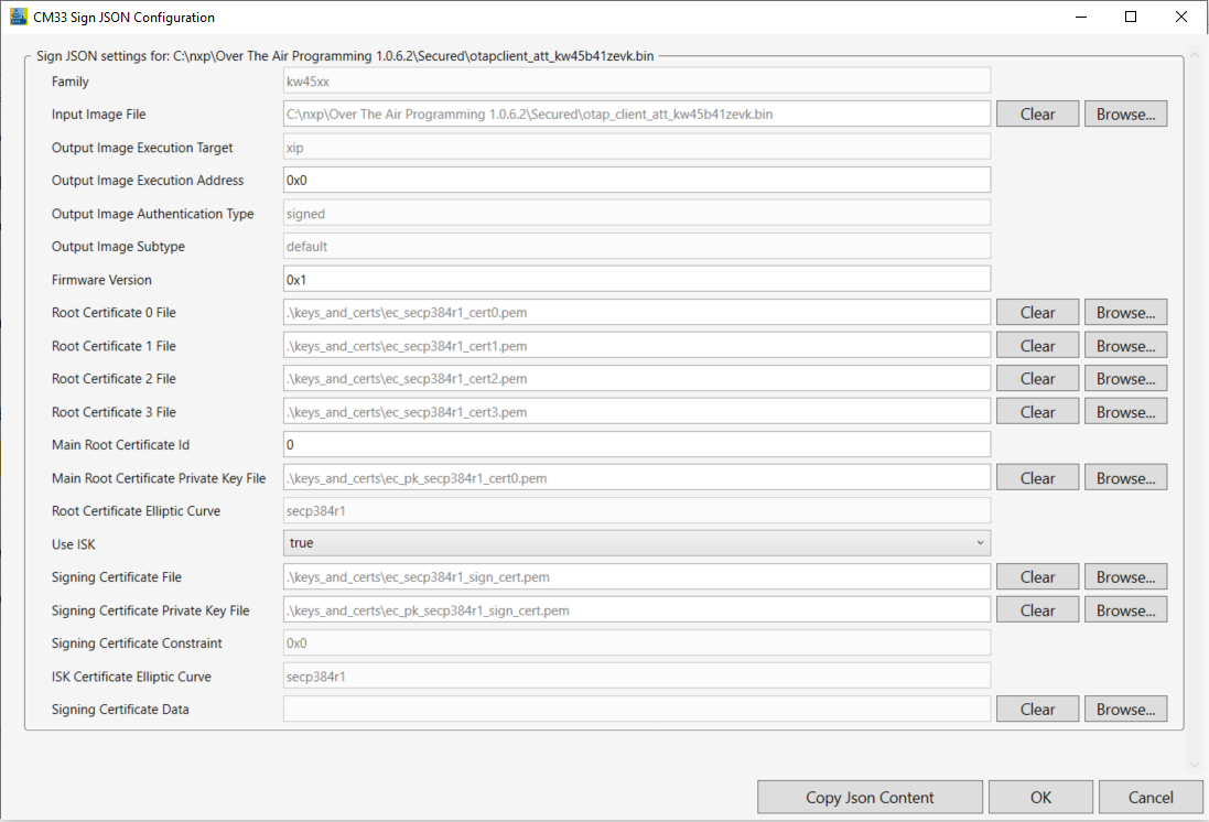
If you select a file that is written on the MCU, a new window appears as shown in the figure below. This window helps in configuring the root certificates and signing the certificates, by either dragging and dropping, or browsing for new files. For details on each field of the JSON, see /Documentation/KW45JsonDescription.pdf provided with Over the Air Programming tool.
By default, the JSON is configured for the demo applications to run as shown in the figure below.
After configuring the JSON file used for signing the MCU file, a new similar window appears. As shown in the Figure 11, the window is designed for configuring the *.sb3 container. This window helps you to configure the encryption key file, the root certificates, and the signing certificates by either drag and dropping or browsing for new files. For details on each field of the JSON file, see /Documentation/KW45JsonDescription.pdf provided with Over the Air Programming tool.
By default, the JSON is configured for the demo applications to run as shown in the figure below.

After the
.sb3file is created, the “Encryption Key” and “Authentication Key” are presented. For the secured update to be successful, the destination board must have been provisioned with these keys through fuse burning, as described in the accompanying document. Depending on the board type, it can either be already provisioned by NXP (KW45B41Z-EVK / K32W148-EVK samples) or not provisioned (loosen samples). See the figure below.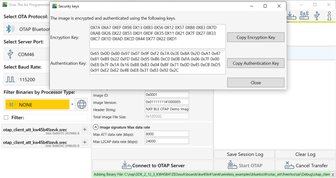
The OTA Header configuration options from the “OTA Header” box are used by the application to build the OTAP Image File, which is sent over the air. The default values of the OTA Header configuration work out of the box for the OTAP demo applications. For details about these configuration options, see the Bluetooth LE Application Developer’s Guide document (BLEADG).
After the image is loaded, go to the “Select Server Port” box, select the correct COM Port for the OTAP Server board. Also select the default baud rate of 115200 and press the “Connect to OTAP Server” button. A successful connection is displayed in the Message Log.
If the image is loaded before connecting to the OATP Server COM Port, then the OTAP Server of the application starts automatically.
If the connection to the COM Port is established before the image is loaded, then the “Start OTAP” button must be pressed to start the OTAP Server of the application. For details, see the figure below.
.
Before starting the image transfer process, the data rate must be configured for each transfer method (ATT or L2CAP CoC). The image chunks of a block are sent over the serial interface and over-the-air without waiting for confirmation. Data rate can significantly slow down if configuration is not done correctly and errors appear in the transfer process.
The optimal data rate depends on multiple factors. Some of these factors are listed below:
Distance between boards
Type of antenna
Performance of the RF circuitry between the radio and antenna
Type and level of noise in the environment
Speed of the storage medium in which the image is saved on the OTAP Client
Serial driver delay between PC and the OTAP Server board If the data rate is too high, then the OTAP Client receives a new chunk before it can process the previous one. In such a case, it sends an “Unexpected Chunk Sequence Number” error and restarts the transfer of the current block from where it left off. If the channel is too noisy, the transmitter can be flooded and some chunks might not reach the client triggering a similar type of error. The default data rate values should work for most configurations.
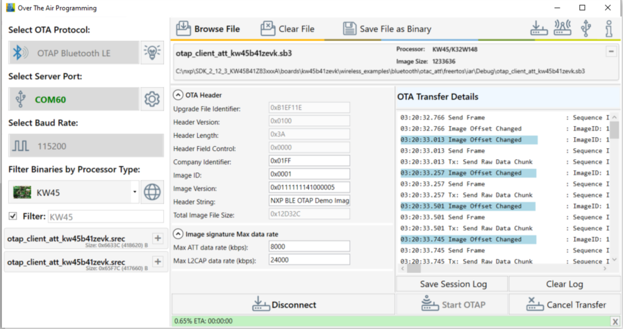
Start the embedded applications by pressing ADVSW first on the OTAP Client and then on the OTAP Server. The transfer progress and transfer-related messages and/or errors are shown in the application window. The duration of the transfer depends on the size of the image and the chosen data rate and transfer method. See the figure below.
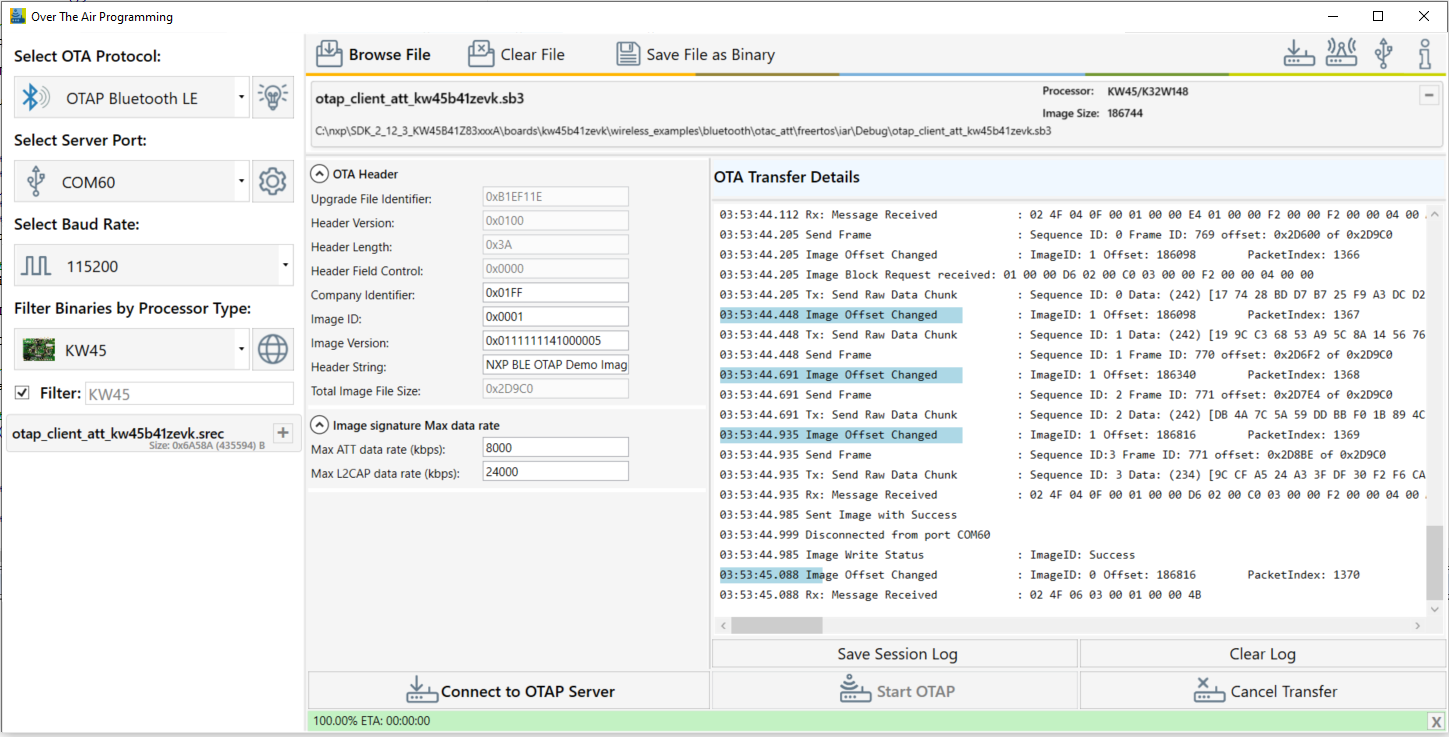
After all the blocks are sent, the OTAP Client sends an
Image Transfer Completecommand to the OTAP Server. When the PC Application receives this command, it displays aSent Image with Successmessage in the log window. See the figure below.
After the image transfer is complete, the OTAP Client triggers the bootloader and resets the MCU. The bootloader takes about 30 seconds to flash the image on the board. After this time frame, the MCU resets again and runs the new image.
Parent topic:Over the Air Programming (OTAP)
Usage with IoT Toolbox
This is the list of requirements.
Mobile device running Android platform or iOS with hardware and software supporting Bluetooth 4.0 and later.
Kinetis Bluetooth LE Toolbox application – download from the specific application store for your device.
To run the application, perform the following steps:
Flash the OTAP Client ATT to either the KW45B41Z-EVK or the K32W148-EVK platform. The Kinetis Bluetooth LE Toolbox only supports the ATT OTAP Client.
In order to send over the air in
.bleotaformat, create the application. In order to load the image file into the Over the Air Programming application and create the .sb3 file, follow the instructions described in Usage with Over The Air Programming Tool. Once the.sb3file is created, press the “Save File as Binary” button to create the.bleotafile. See the figure below.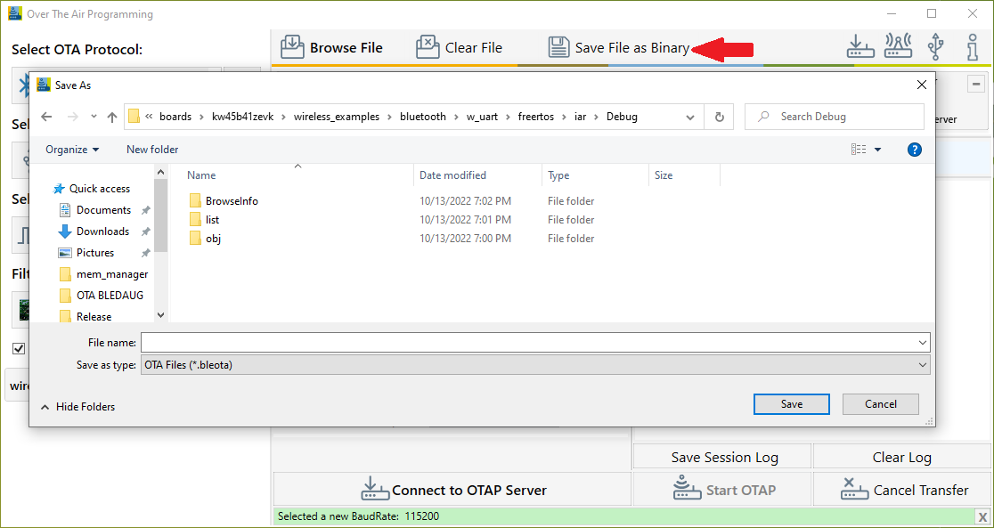
Start the Kinetis Bluetooth LE Toolboxapplication on your mobile device and start the OTAP Tool. The application starts scanning.
Press ADVSW on the board to start Advertising on the embedded OTAP Client application. The device should show up in the list of scanned devices. Touch the device in the scan list to connect to and the application performs service discovery and displays some information shown in the figure below.

Press the “Open” button and load the
.bleotafile to be sent over-the-air. Once the file is loaded, some information about it is displayed. Press the “Upload” button to start the image transfer process. A progress bar is shown while the image transfer is ongoing. The progress bar displays 100% update after a successful transfer, as shown in the figure below.
After the image transfer is complete, the OTAP Client triggers the bootloader and resets the MCU. The bootloader takes about 30 seconds to flash the image on the board. After this time passes, the MCU resets again and runs the new image.
Parent topic:Over the Air Programming (OTAP)
Parent topic:Bluetooth LE stack and demo applications