Overview
The NXP Serial Memory Tool is a Visual Studio Code extension that streamlines serial memory configuration and validation for NXP microcontrollers. With an intuitive graphical interface, developers can easily configure memory parameters, validate settings on real hardware, and generate FCB binaries—all without leaving VS Code.
Note: This user guide is for NXP Serial Memory Tool version 26.06. For the latest updates and information, check the extension marketplace page.
Note: The software is subject to the NXP software license agreement.
Key features
Serial memory configuration and validation
Real-time validation
Integration with Visual Studio Code
Import/save capability
FCB generation (for supported devices)
User-friendly UI for creating and modifying the memory lookup table
Link a C project to apply configurations changes (for supported devices)
Provides automatic memory‑chip parameter discovery via the SFDP Test (for supported devices)
Simplified configuration mode using configuration words, providing an alternative to the Advanced configuration mode (for supported devices)
Collapse/Expand all configuration sections for streamlined navigation
Filter settings search box to quickly locate specific configuration parameters
Scroll to top button for easy navigation in long configuration views
Settings modification counter with reset to default option
Validation marker in top right side to show the current configuration status - Valid, Invalid
GitHub Copilot Integration (requires VS Code 1.99+) — Configure device, memory, and mode directly from the Copilot Chat panel using natural language, guided wizards, or AI-driven agent mode (Experimental)
System requirements
Supported operating systems
Windows 11 (64-bit)
Software requirements
Visual Studio Code (the latest version is recommended)
Python environment (the tool configures this automatically)
Hardware support
i.MX RT101x series
i.MX RT102x series
i.MX RT1024 series
i.MX RT105x series
i.MX RT118x series
i.MX RT7xxx series
RW61x series
Installation
Installing the extension
Open Visual Studio Code
Go to the Extensions view (Ctrl+Shift+X)
Search for “Serial Memory Tool for VS Code”
Click Install
Setting up the Python environment
After installation, the Install Toolchain button appears in the tool interface.
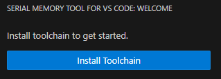
To automatically set up the preconfigured Python environment, click the button.
Wait for the installation to complete (this process may take several minutes).

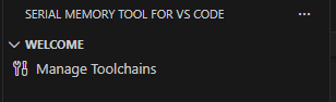
Once the installation is complete, the tool interface will be fully loaded and ready to use. The Welcome page will display the Manage Toolchains option, which allows you to manage your toolchain installation.
Getting started
Working with Serial Memory Tool
1. Open VS Code
Launch Visual Studio Code on your system
2. Access the Serial Memory Tool
Look for the NXP tool icon in the Activity Bar
![]()
Or open the Command Palette (Ctrl+Shift+P) and search for “Serial Memory Tool”
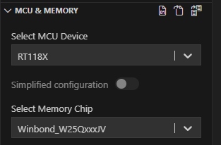
3. Select the target device
Select a processor from the supported devices list.
Once a processor is selected, a default Memory Chip is automatically assigned. This chip comes with a standard configuration validated on the EVK board.
For supported devices, a toggle button enables switching between Simplified and Advanced configuration modes.
If the Memory Chip is changed, the memory type is updated automatically in the Configuration page to match the new selection.

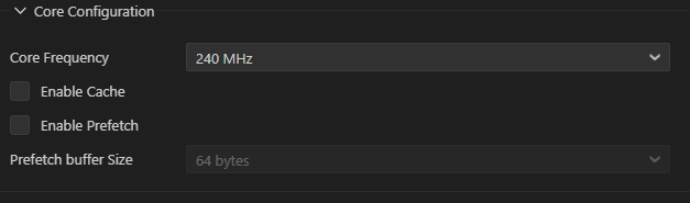
4. Use the default configuration or create a custom configuration
EVK configuration is set by default for the selected device.
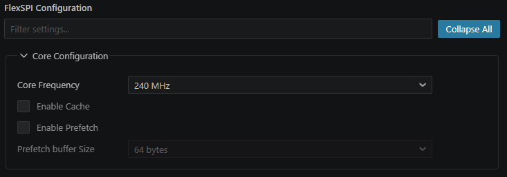
Core configuration allows you to modify core-specific paramaters as frequency, caches and prefetch.
4.1. Advanced configuration mode
Provides full control over memory parameters.
If needed, adjust the configuration of Memory, FlexSPI Connection, Memory LUT.
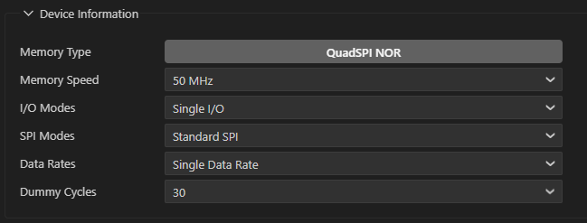
Memory Information Configuration
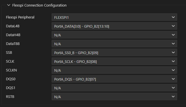
FlexSPI Connection Configuration
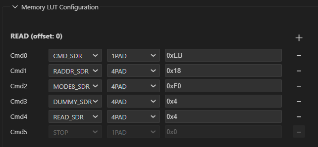
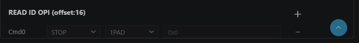
Memory LUT Configuration provides the option to add or remove LUT commands as it is needed for advanced memory configurations.
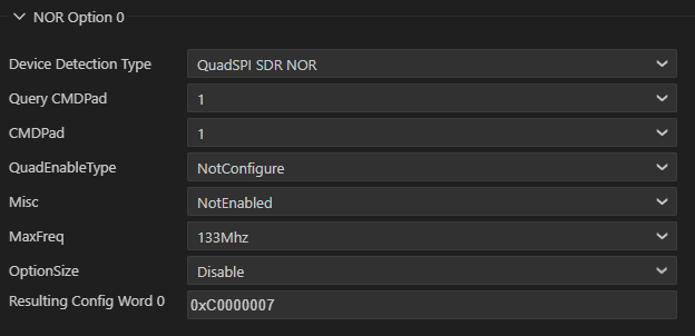
4.2. Simplified configuration mode
This mode is intended for standard configurations and reduces complexity compared to Advanced mode
Select configuration words from the drop-down menu to quickly apply predefined memory settings
4.3. Configuration navigation and management tools
Collapse/Expand All — Use the collapse/expand toggle to show or hide all configuration sections at once. This is useful when working with large configurations and you want to focus on specific sections.
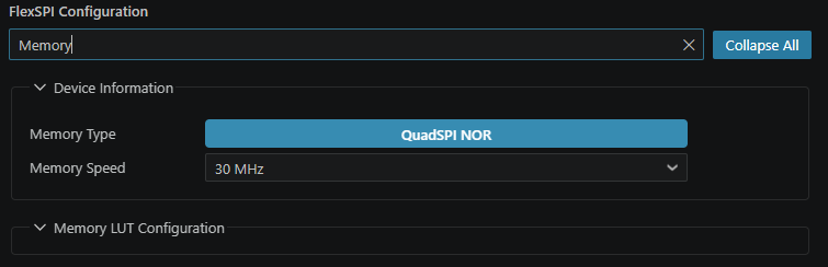
Filter Settings — Use the search box at the top of the Configuration panel to filter settings by name. As you type, only matching parameters are displayed, making it easy to locate a specific setting without scrolling through all sections.
Scroll to Top — When scrolling down through the configuration, a Scroll to Top button appears, allowing you to quickly return to the top of the Configuration panel. Clicking it scrolls the view back to the top of the panel instantly.
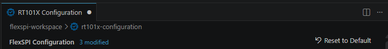
Modification Counter and Reset to Default — A counter displays the number of settings that have been modified from their default values. Click the Reset to Default button to restore all configuration parameters to their original default values for the selected device and memory chip.
4.4. To save any configuration changes, press Ctrl+S or navigate to File->Save.
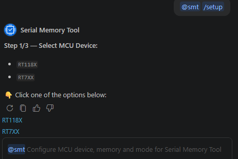
5. Working with GitHub Copilot (Experimental)
The Serial Memory Tool integrates with GitHub Copilot Chat, allowing you to configure your device setup directly from the chat panel using
@smt.
Interaction Modes
Mode |
Command |
Description |
|---|---|---|
Guided Wizard |
|
Step-by-step configuration with clickable follow-up buttons |
Quick Setup |
|
Fast configuration using VS Code dropdown menus |
Natural Language |
|
Set device, mode, or memory using plain English |
Status |
|
Show current configuration summary |
Agent Mode |
Free text in Agent mode |
Copilot autonomously calls the right tools |
Guided wizard — type @smt /setup and follow the clickable buttons:
Natural language — configure everything in one sentence:

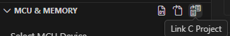
6. Link a SDK C project (optional)
Click the Link C Project button to associate the current configuration with an SDK C project.
Select the project folder containing the SDK C project files.
Once linked, Editing mode is enabled for configuration modifications. All modified files will be listed in the Modified Files section.
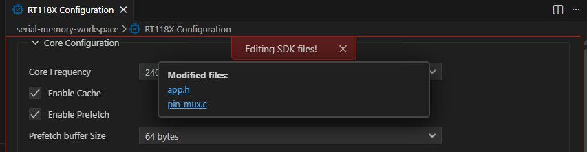
Changes are highlighted in the project explorer and can be reviewed before validation.
7. Board detection
Before connecting, ensure the board is configured to boot in Serial Downloader mode.
Connect one cable to the USB_OTG1 for the Serial Downloader interface and the second cable to the Debug USB port for UART communication.
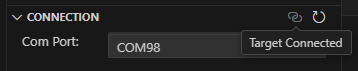
A connected board can be detected using the “Refresh current connection” button available in the Connection group.
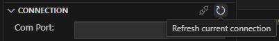
Choose the appropriate COM port in case multiple boards are connected.
The connection icon changes and indicates the Connected status once the board is detected.
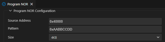
8. Validate configuration by executing tests on the target
Configure test parameters:
Click Test, the Test Configuration tab opens to the right.
To modify test settings, change test parameters.
Upon test parameters changing, validation errors can be displayed in case the selected parameters are not correct.
Execute test:
Tests cannot be executed unless a board is detected (the Run Test button is disabled).
Once a board is detected, the tests Run button gets enabled (green icon).
Click the Start button to start the test execution.
The pass / Fail status icon is displayed in the left side of the tests tree after the test finishes executing.
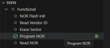
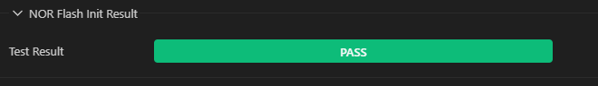
Test result is also displayed in the Test Result panel.
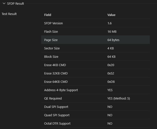
For the SFDP test, a detailed report is generated showing memory parameters detected from the device.
9. Test logging
The Test execution log is displayed in the Serial Memory Tool for VS Code console that automatically opens at the bottom when a test starts.
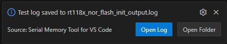
Upon test completion, a summary report is generated displaying the overall test results. A notification appears with options to open the log file or log folder.
10. Import configuration
The Import button is located in the top-right corner in the “MCU & Memory” panel.
Imported -> A saved configuration can be imported using the import button.

11. Generate FCB
The FCB button is available in the top-right corner in the “MCU & Memory” panel.
To generate and save FCB binary, use the Generate FCB button.

Basic workflow
Start Tool → Select MCU and Memory Chip → Configure Memory Settings → Board detection → Validate Configuration by executing tests on target -> Generate FCB or save configuration
User interface overview
Main interface components
Welcome Panel
The Welcome Panel is located in the top-right corner of the interface and serves as the starting point for toolchain management and initial setup. It provides access to options such as installing and managing the toolchain, allowing users to configure their development environment. Through this panel, it is possible execute commands to install the toolchain, uninstall it if needed, and check for available updates to ensure the setup remains current and functional.
Device selection panel (MCU & Memory)
This panel is located at the top of the interface, making it easily accessible as the starting point for configuration. The panel allows choosing the target microcontroller unit (MCU) and the memory chip you intend to work with. This selection is essential for tailoring the configuration and generation process to your specific hardware setup. Currently, the RT1180 microcontroller is available for selection. Additional devices will be supported in future updates.
Panel sections:
MCU Device selection: Choose the microcontroller that matches your project requirements.
Memory Chip selection: Select the memory chip that will be paired with the chosen MCU.
Import / Save / Generate FCB Buttons: Use these buttons to import existing configurations, save your current setup, or generate the Flash Configuration Block (FCB) based on your selections.
Configuration panel
The Configuration Panel is located in the center area of the interface and is used to set up parameters for serial memory.
Panel sections:
Core Configuration
Memory Information Configuration
FlexSPI connection configuration
Memory LUT Configuration
Panel tools:
Collapse/Expand All: A toggle control that collapses or expands all configuration sections simultaneously. When collapsed, only section headers are visible, providing a compact overview. When expanded, all parameters within each section are displayed for detailed editing.
Filter Settings: A search box located at the top of the Configuration panel. Typing a keyword filters the visible settings in real time, showing only parameters whose names match the search query. Clear the search box to restore the full view.
Scroll to Top: A floating button that appears automatically when the user scrolls down within the Configuration panel. Clicking it scrolls the view back to the top of the panel instantly.
Modification Counter and Reset to Default: A badge or indicator that shows how many configuration parameters have been changed from their default values. Next to it, a Reset to Default button restores all settings to the factory defaults for the currently selected device and memory chip combination. This is useful when experimenting with configurations and you need to return to a known good state.
Tests panel
The Tests Panel is located on the right side of the center area and is designed to display validation results and errors. It features validation, providing feedback on the correctness of the configuration, and indicates whether the current setup passes or fails. This helps users identify and resolve issues, ensuring an accurate configuration process.
Connection panel
The Connection Panel is located at the bottom right side of the interface and is used to detect whether a development board is connected. It shows the current connection status and allows users to manually refresh the connection by clicking the Refresh connection button. This helps ensure that the system is properly linked to the hardware before proceeding with further configuration or testing.
Troubleshooting
This chapter contains known problems and recommended solutions.
Issue: tool does not start
Symptoms: Extension loads but the tool interface does not appear.
Solutions:
Restart VS Code
Check if Python environment is properly installed
Run “Manage Toolchain” and Reset Toolchain
Reinstall Toolchain using “Install Toolchain” button
Check VS Code output panel for error messages
Issue: device is not recognized
Symptoms: RT1180 does not appear in the device list.
Solutions:
Make sure to use a supported Windows version
Update the extension to the latest version
Check system requirements
Known issues and limitations
This chapter contains limitations and possible workaround.
Current limitations
Operating system support:
Currently supported only on Windows 10/11 (64-bit)
macOS and Linux support is available in future releases
Device support:
Limited to RT11xx and RT7xx microcontroller families
Additional device support is in development
Feature limitations:
FCB generation is currently limited to RT11xx devices
SFDP test table generation is currently limited to RT11xx devices
Linking a C project is currently limited to RT11xx devices
Simplified mode is currently limited to RT11xx devices
Workarounds
Unsupported operating systems
Use a Windows virtual machine
Wait for future OS support updates
Additional device support
Check for extension updates regularly
Contact NXP support for roadmap information
References
Documentation:
RT1180 reference manual
RT700 reference manual
Online resources:
Technical support:
Revision history
Document ID |
Release date |
Description |
|---|---|---|
UG10328 v.5.0 |
30 June 2026 |
Updated for 26.06. |
UG10328 v.5.0 |
31 May 2026 |
Updated for 26.05. |
UG10328 v.4.0 |
30 April 2026 |
Updated for 26.04. |
UG10328 v.3.0 |
31 March 2026 |
Updated for 26.03. |
UG10328 v.2.0 |
12 December 2025 |
Updated for 25.12. |
UG10328 v.1.0 |
4 December 2025 |
Initial version. |
Note about the source code in the document
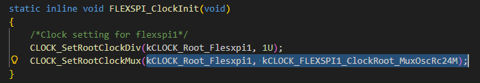
Example code shown in this document has the following copyright and BSD-3-Clause license:
Copyright 2026 NXP Redistribution and use in source and binary forms, with or without modification, are permitted provided that the following conditions are met:
Redistributions of source code must retain the above copyright notice, this list of conditions and the following disclaimer.
Redistributions in binary form must reproduce the above copyright notice, this list of conditions and the following disclaimer in the documentation and/or other materials provided with the distribution.
Neither the name of the copyright holder nor the names of its contributors may be used to endorse or promote products derived from this software without specific prior written permission.
THIS SOFTWARE IS PROVIDED BY THE COPYRIGHT HOLDERS AND CONTRIBUTORS “AS IS” AND ANY EXPRESS OR IMPLIED WARRANTIES, INCLUDING, BUT NOT LIMITED TO, THE IMPLIED WARRANTIES OF MERCHANTABILITY AND FITNESS FOR A PARTICULAR PURPOSE ARE DISCLAIMED. IN NO EVENT SHALL THE COPYRIGHT HOLDER OR CONTRIBUTORS BE LIABLE FOR ANY DIRECT, INDIRECT, INCIDENTAL, SPECIAL, EXEMPLARY, OR CONSEQUENTIAL DAMAGES (INCLUDING, BUT NOT LIMITED TO, PROCUREMENT OF SUBSTITUTE GOODS OR SERVICES; LOSS OF USE, DATA, OR PROFITS; OR BUSINESS INTERRUPTION) HOWEVER CAUSED AND ON ANY THEORY OF LIABILITY, WHETHER IN CONTRACT, STRICT LIABILITY, OR TORT (INCLUDING NEGLIGENCE OR OTHERWISE) ARISING IN ANY WAY OUT OF THE USE OF THIS SOFTWARE, EVEN IF ADVISED OF THE POSSIBILITY OF SUCH DAMAGE.
Legal information
Definitions
Draft — A draft status on a document indicates that the content is still under internal review and subject to formal approval, which may result in modifications or additions. NXP Semiconductors does not give any representations or warranties as to the accuracy or completeness of information included in a draft version of a document and shall have no liability for the consequences of use of such information.
Disclaimers
Limited warranty and liability — Information in this document is believed to be accurate and reliable. However, NXP Semiconductors does not give any representations or warranties, expressed or implied, as to the accuracy or completeness of such information and shall have no liability for the consequences of use of such information. NXP Semiconductors takes no responsibility for the content in this document if provided by an information source outside of NXP Semiconductors.
In no event shall NXP Semiconductors be liable for any indirect, incidental, punitive, special or consequential damages (including - without limitation - lost profits, lost savings, business interruption, costs related to the removal or replacement of any products or rework charges) whether or not such damages are based on tort (including negligence), warranty, breach of contract or any other legal theory.
Notwithstanding any damages that customer might incur for any reason whatsoever, NXP Semiconductors’ aggregate and cumulative liability towards customer for the products described herein shall be limited in accordance with the Terms and conditions of commercial sale of NXP Semiconductors.
Right to make changes — NXP Semiconductors reserves the right to make changes to information published in this document, including without limitation specifications and product descriptions, at any time and without notice. This document supersedes and replaces all information supplied prior to the publication hereof.
Suitability for use — NXP Semiconductors products are not designed, authorized or warranted to be suitable for use in life support, life-critical or safety-critical systems or equipment, nor in applications where failure or malfunction of an NXP Semiconductors product can reasonably be expected to result in personal injury, death or severe property or environmental damage. NXP Semiconductors and its suppliers accept no liability for inclusion and/or use of NXP Semiconductors products in such equipment or applications and therefore such inclusion and/or use is at the customer’s own risk.
Applications — Applications that are described herein for any of these products are for illustrative purposes only. NXP Semiconductors makes no representation or warranty that such applications will be suitable for the specified use without further testing or modification.
Customers are responsible for the design and operation of their applications and products using NXP Semiconductors products, and NXP Semiconductors accepts no liability for any assistance with applications or customer product design. It is customer’s sole responsibility to determine whether the NXP Semiconductors product is suitable and fit for the customer’s applications and products planned, as well as for the planned application and use of customer’s third party customer(s). Customers should provide appropriate design and operating safeguards to minimize the risks associated with their applications and products.
NXP Semiconductors does not accept any liability related to any default, damage, costs or problem which is based on any weakness or default in the customer’s applications or products, or the application or use by customer’s third party customer(s). Customer is responsible for doing all necessary testing for the customer’s applications and products using NXP Semiconductors products in order to avoid a default of the applications and the products or of the application or use by customer’s third party customer(s). NXP does not accept any liability in this respect.
Terms and conditions of commercial sale — NXP Semiconductors products are sold subject to the general terms and conditions of commercial sale, as published at https://www.nxp.com/profile/terms, unless otherwise agreed in a valid written individual agreement. In case an individual agreement is concluded only the terms and conditions of the respective agreement shall apply. NXP Semiconductors hereby expressly objects to applying the customer’s general terms and conditions with regard to the purchase of NXP Semiconductors products by customer.
Export control — This document as well as the item(s) described herein may be subject to export control regulations. Export might require a prior authorization from competent authorities.
Suitability for use in non-automotive qualified products — Unless this document expressly states that this specific NXP Semiconductors product is automotive qualified, the product is not suitable for automotive use. It is neither qualified nor tested in accordance with automotive testing or application requirements. NXP Semiconductors accepts no liability for inclusion and/or use of non-automotive qualified products in automotive equipment or applications.
In the event that customer uses the product for design-in and use in automotive applications to automotive specifications and standards, customer (a) shall use the product without NXP Semiconductors’ warranty of the product for such automotive applications, use and specifications, and (b) whenever customer uses the product for automotive applications beyond NXP Semiconductors’ specifications such use shall be solely at customer’s own risk, and (c) customer fully indemnifies NXP Semiconductors for any liability, damages or failed product claims resulting from customer design and use of the product for automotive applications beyond NXP Semiconductors’ standard warranty and NXP Semiconductors’ product specifications.
HTML publications — An HTML version, if available, of this document is provided as a courtesy. Definitive information is contained in the applicable document in PDF format. If there is a discrepancy between the HTML document and the PDF document, the PDF document has priority.
Translations — A non-English (translated) version of a document, including the legal information in that document, is for reference only. The English version shall prevail in case of any discrepancy between the translated and English versions.
Security — Customer understands that all NXP products may be subject to unidentified vulnerabilities or may support established security standards or specifications with known limitations. Customer is responsible for the design and operation of its applications and products throughout their lifecycles to reduce the effect of these vulnerabilities on customer’s applications and products. Customer’s responsibility also extends to other open and/or proprietary technologies supported by NXP products for use in customer’s applications. NXP accepts no liability for any vulnerability. Customer should regularly check security updates from NXP and follow up appropriately.
Customer shall select products with security features that best meet rules, regulations, and standards of the intended application and make the ultimate design decisions regarding its products and is solely responsible for compliance with all legal, regulatory, and security related requirements concerning its products, regardless of any information or support that may be provided by NXP.
NXP has a Product Security Incident Response Team (PSIRT) (reachable at PSIRT@nxp.com) that manages the investigation, reporting, and solution release to security vulnerabilities of NXP products.
NXP B.V. — NXP B.V. is not an operating company and it does not distribute or sell products.
Trademarks
Notice: All referenced brands, product names, service names, and trademarks are the property of their respective owners.
NXP — wordmark and logo are trademarks of NXP B.V.