Bootable image generation
RT1180 can only boot from CM33. For CM33 application image to boot, a sophisticated boot header structure is needed. To ease the customer from complex settings, the Secure Provisioning Tool is provided. Among other rich features, it provides an easy way to use GUI for customer to generate bootable image from raw application image. In addition, in order for users to run the CM7 image conveniently, SDK provides the multicore_trigger demo for users to kick off CM7 image, combined with the SPT tool, we can run CM7 image by from POR.
In this section, two kinds of images are defined
Terminology |
Description |
|---|---|
RAW image |
Demo image without boot header |
POR image |
Demo image with boot header |
Most examples that we provided in SDK package create RAW images from project settings. Only some OOBE examples can create POR image. POR image can provide good out-of-box experience, but the cost is losing some flexibility. While RAW images, with the usage of Secure Provisioning Tool, have the most widely usage like image signning, multiple image combination, and so on. For demos that by default generate a POR boot image, see RAW/POR image switch.
Use SPT tool to boot cm33 image
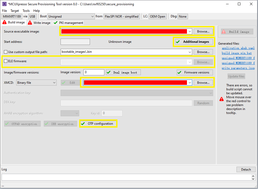
Run the Secure Provisioning Tool, and the following GUI shows.
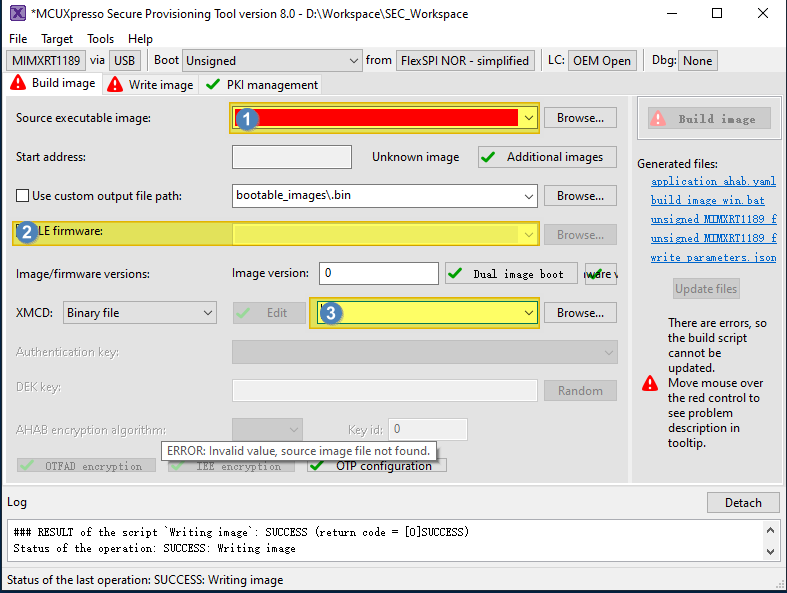
Select the following items:
Toolchain generated images
All SDK generated images are supported no matter they boot from TCM, FlexSPI Nor, or HyperRAM.
Toolchain
Suffix
ARMGCC
.elf
IAR
.out
MDK
.out/.hex
MCUX
.axf
Note:
Use the RAW image for CM33. Some SDK project targets are POR image by default, it must to be switched to RAW image for SPT usage. For more information, see RAW/POR image switch.
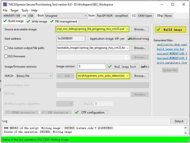
It is recommended to use elf/out files, thus SPT can parse the Start address automatically.
XMCD file
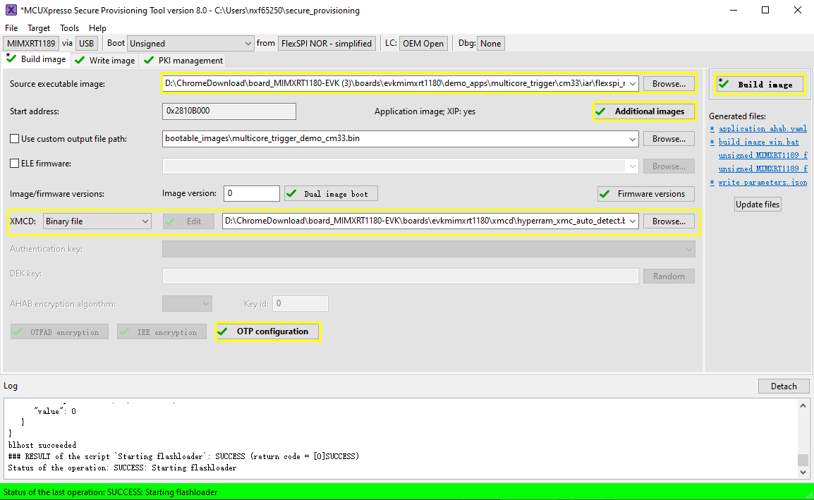
This is on-board SDRAM/HyperRAM initialization file. For the RT1180 EVK board, select boards/evkmimxrt1180/xmcd/hyperram_xmc_auto_detect.bin.
Note:
If the application image uses
hyperram(target hyperram_debug/release, flexspi_hyperram_debug/release, hyperram_txt_debug/release), the XMCD is necessary.hyperram_xmc_auto_detect.bin is board specific.
(Optional) ELE firmware
This is needed for certain application images which need special ELE FW service. For most SDK demos, simply leave it empty.
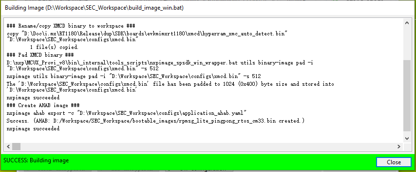
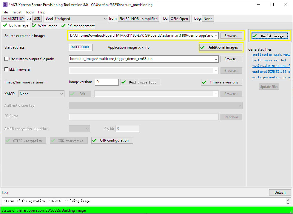
After the selection, click Build Image to generate the bootable image (POR image).
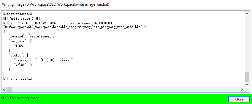
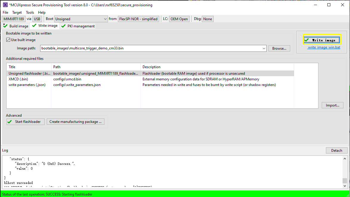
Now switch to the Write Image tab. All information is automatically generated from the previous page. Connect both USB OTG1 port (J33) and MCU-Link port (J53) to the computer and power up the board (or reset via SW3). Make sure that the EVK board boot configuration switch SW5[1..4] are on 0001 SDP mode and click Write Image.
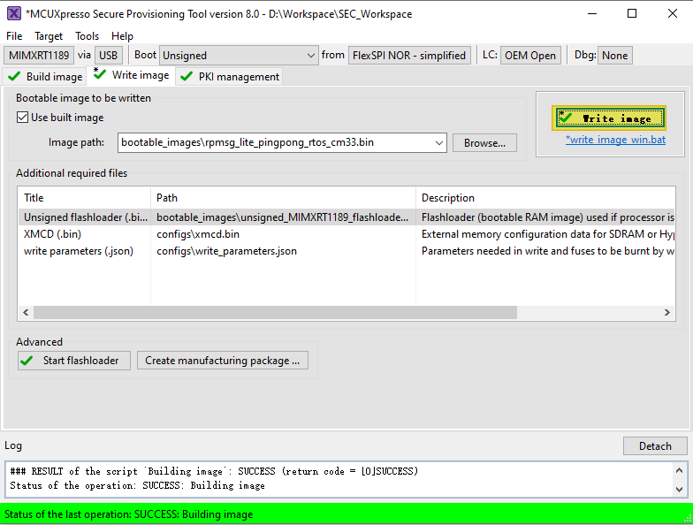
Change the SW5[1..4] to QSPI boot mode 0100 and reset the board, and then you can observe that the image is running from POR boot.
Parent topic:Bootable image generation
Use SPT tool and multicore_trigger image to kick off cm7 binary image
This section introduces how to create a CM7 POR boot image with the aid of a CM33 kicker application. The CM33 kicker application is located in demo_apps/multicore_trigger.
For a secure provisioning tool to generate such a bootable CM7 image, specify the CM33 multicore_trigger image in Source executable image. The CM7 application image to be kicked off must be specified with additional images.
CM7 XIP image runs from external FLASH, and multicore_trigger CM33 image runs from internal RAM
Perform the following steps:
Prepare the
multicore_trigger_demo_cm33ram image (debugorreleasetargets) and specify it inSource executable image.Specify the XMCD file if necessary (see Use SPT tool and multicore_trigger image to kick off cm7 binary image).
Use
Additional imagesto specify CM7 application image running from flash memory. See Table 1 for how to fill in the necessary information for this additional image.Parameter
Explanation
Image offset
0xA000
The offset in bytes from start of the current container header to beginning of the image. In our case, the CM7 image is flashed to 0x2800_B000. The container header is put to 0x2800_1000 and the yield offset = 0xA000.
|
|Load address|0x2800B000
The destination address of the CM7 image. ROM copies the image to load address, if it is not within flash address space. In our case, copy does not happen.
|
|Entry point|0x2800B000
The start address of CM7 image vector table from CM7 core address space.
| |Core ID|cortex-m7| |Image type|Executable| |Encrypted|No|

(Optional) ELE firmware.
It is needed for a certain application image, which need special ELE FW service. For most SDK demos, simply leaves it empty.
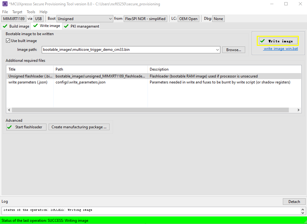
After a successful write, change the SW5[1..4] to QSPI boot mode 0100 and reset the board. You can observe that the image is running from POR boot.
Parent topic:Use SPT tool and multicore_trigger image to kick off cm7 binary image
CM7 binary image runs from internal TCM, and multicore_trigger CM33 image runs from external FLASH
Note: Be very careful that this scenario requires fuse manipulation, which is not revertible.
Prepare the
multicore_trigger_demo_cm33flash target image (flexspi_nor_debugorflexspi_nor_release) and specify it inSource executable image.Use
Additional imagesto specify CM7 application image running from ITCM memory. See Table 1 for how to fill in necessary information for this additional image.Parameter
Explanation
Image offset
0xA000
The flash allocation is the same as previous scenario.
|
|Load address|0x303C0000
This is the secured alias of CM7 ITCM in CM33/ROM memory space. ROM will copy image to this address.
|
|Entry point|0x0
The start address of vector table from CM7 core address space.
|
|Core ID|cortex-m7|
|Image type|Executable|
|Encrypted|No|

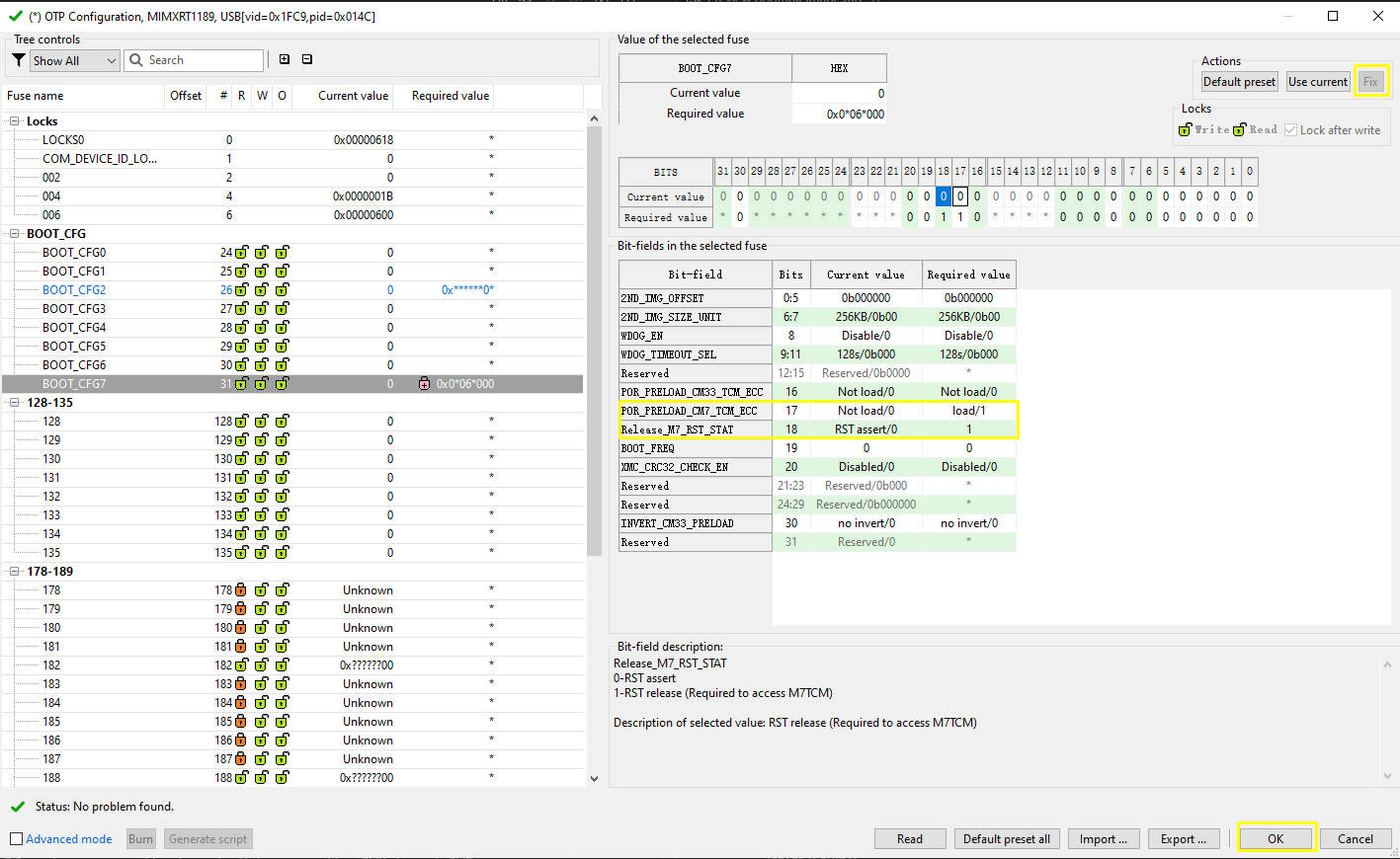
For ROM to successful copy image from flash to CM7 TCM. CM7 TCM ECC should be pre-configured. To archive this, a Fuse need to be set. Click OTP configuration, set
POR_PRELOAD_CM7_TCM_ECCandRELEASE_M7_RST_STATfuses inBOOT_CFG7to 1.Note: Be very careful that any setting on OTP won’t be reverted once set. There is possibility that the chip get bricked if you are fusing the wrong fuse word. Only do this if you really need to try this boot scenario.
(Optional) ELE firmware.
It is needed for a certain application image which needs a special ELE FW service. For most SDK demos, simply leave it empty.
After a successful write, change the SW5[1..4] to QSPI boot mode 0100 and reset the board. You can observe that the image is running from the POR boot.
Note:
The new image constructed under Build images is still not a complete image, and the Memory Configuration Block is missing. When writing image, SPT downloads the contents of the Memory Configuration Block to FLASH.
When CM33 + CM7 image runs with the following target combination, it is required to set
CM33_SET_TRDCto 1U inmulticore_triggerdemo, also requires to setCM33_SET_TRDCto 1U in CM7 demo if it exists.- CM33 flexspi + CM7 flexspi, flexspi means flexspi_nor_debug/release, flexspi_nor_sdram_debug/release, flexspi_nor_hyperram_debug/release - CM33 HYPERRAM + CM7 HYPERRAM, HYPERRAM means hyperram_txt_debug/release.
Only those
cm7projects whose linkages are similar withhello_world_demo_cm7, support POR run viamulticore_trigger_cm33.
Parent topic:Use SPT tool and multicore_trigger image to kick off cm7 binary image
Parent topic:Bootable image generation
RAW/POR image switch
In current delivered SDK package, most demos generate RAW images. To enhance customer OOBE experience, the following RT1180 SDK CM33 project/targets generate POR image, which means that they can POR run after you debug/download it in IDE.
IAR/GCC/MDK, hello_world_demo_cm33 flexspi_nor_debug/release, flexspi_nor_hyperram_debug/release
IAR/GCC/MDK, multicore_hello_world_cm33 flexspi_nor_debug/release, flexspi_nor_hyperram_debug/release
MCUX CM33 image are all POR images except the
multicore_triggerdemo.
Note:
These POR images are not signed, just for develop convenience, not recommended for product usage.
It is highly recommended to use SPT for image download.
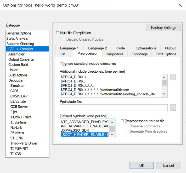
For the SDK CM33 IAR/MDK/ARMGCC project, flexspi_nor targets, as well as for MCUX project, debug/release targets. It is easy to switch RAW/POR image, via the project macro XIP_BOOT_HEADER_ENABLE setting. Table 1describes the rules.
XIP_BOOT_HEADER_ENABLE setting |
Image type |
|---|---|
1 |
POR |
0 |
RAW |
For IAR/ARMGCC, change the macro
XIP_BOOT_HEADER_ENABLEin the compiler setting.For MDK, change the macro
XIP_BOOT_HEADER_ENABLEin compiler and link setting simultaneously.
For detailed settings, see the following sections.
IAR settings for image type switch
Parent topic:RAW/POR image switch
ARMGCC settings for image type switch
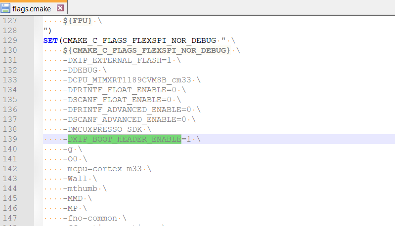
Parent topic:RAW/POR image switch
MDK setting for image type switch
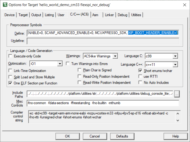
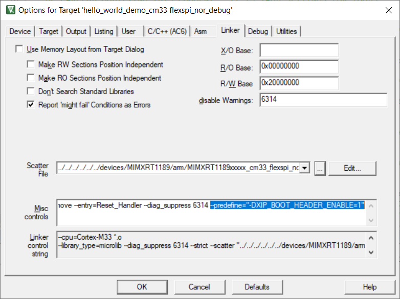
Parent topic:RAW/POR image switch
MCUxpresso settings for image type switch
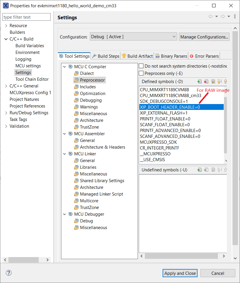
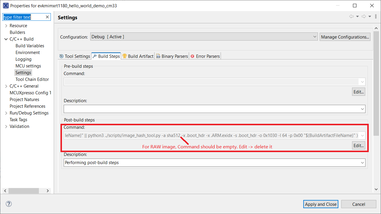
Parent topic:RAW/POR image switch
Parent topic:Bootable image generation
Use Secure Provisiong Tool to erase flash
In worst cases a debugger cannot successfully connect to the board. A major reason for this is there are POR boot image inside the on board flash memory which causes the whole system in a trouble state. Secure Provisioning Tool provide a reliable way to erase the flash in this worst case. To achieve this
Set SW5[1:4] to
0001.Connect the board to your PC from both
J53(Debugging) andJ33(USB OTG 1), then power up the board.Start
Secure Provisioning Tool, selectTool>Flash ProgrammerorCtrl + R.Click
Yesto prompt up questions, wait memory initialization finish.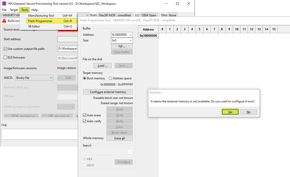
Click
Erase allbutton and wait a minute for the erase process to finish.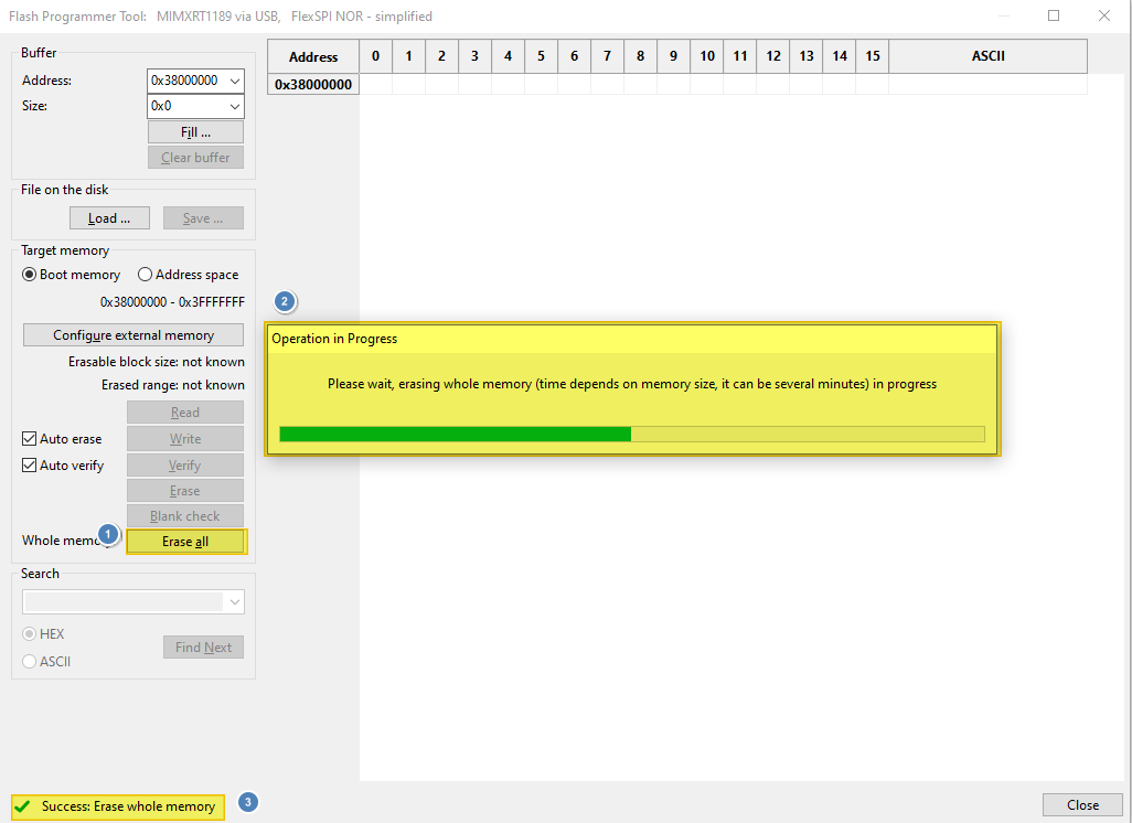
After
Success: Erase whole memoryshows up, the board should have restored to a good state to work in various mode.
Parent topic:Bootable image generation