TwinCAT project setup
This section lists the steps to set up the TwinCAT project.
Create a new project
Import the ESI file of the servo motor example before TwinCAT starts.
Copy the ESI file ‘
ECAT-SERVO-MOTOR.xml’ generated by SSC tool under the SSC project saving directory to<TwinCAT_installation_folder>/<Version>/Config/io/EtherCAT/.Select File > New > Project.
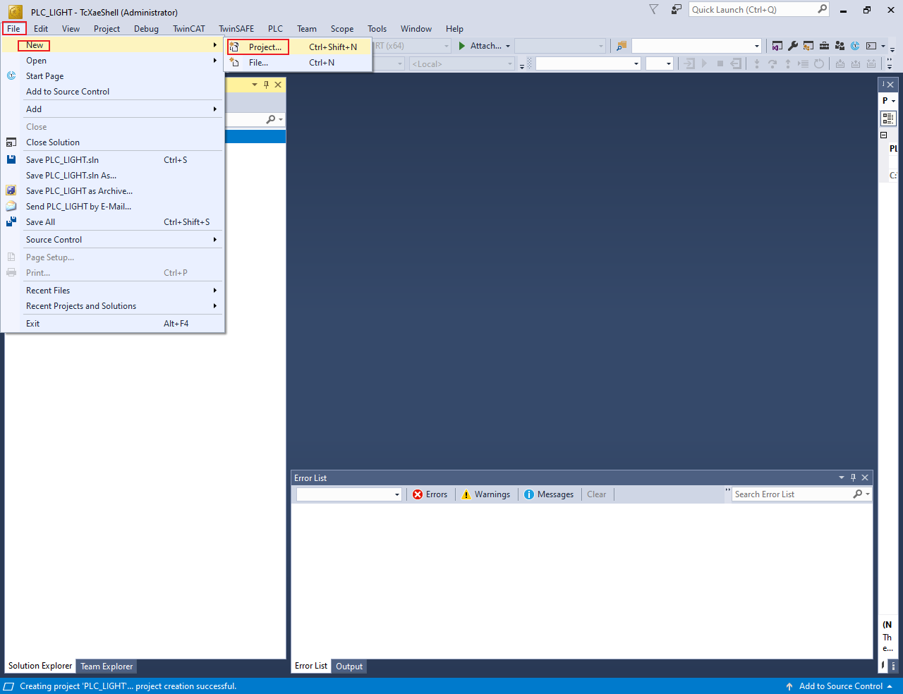
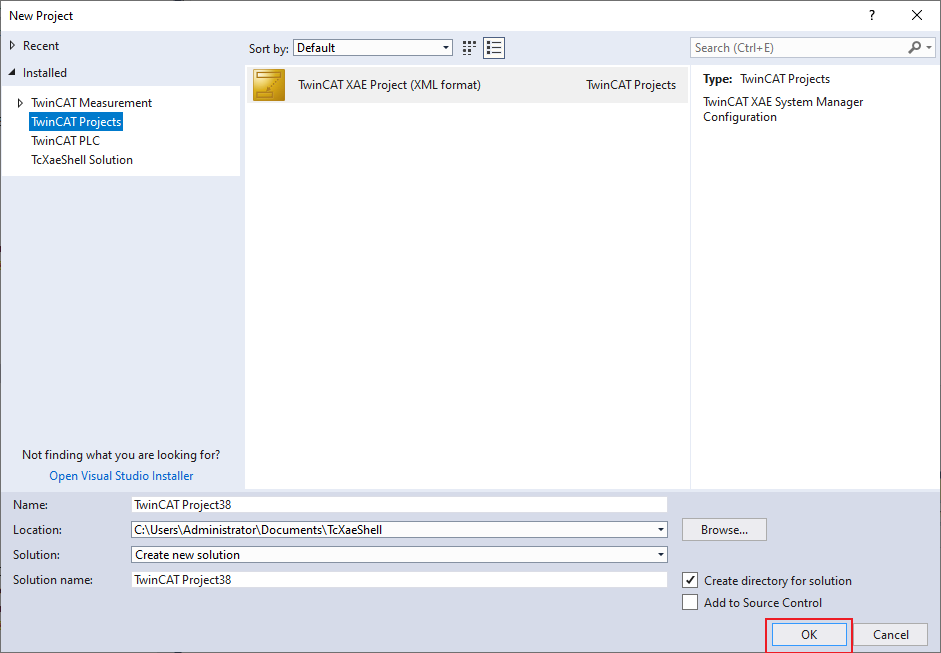
The New Project dialog box appears.
Select TwinCAT Projects.
Click OK.
Scan the for subdevices
In the Solution Explorer view, expand I/O.
Right-click on Device and select Scan.
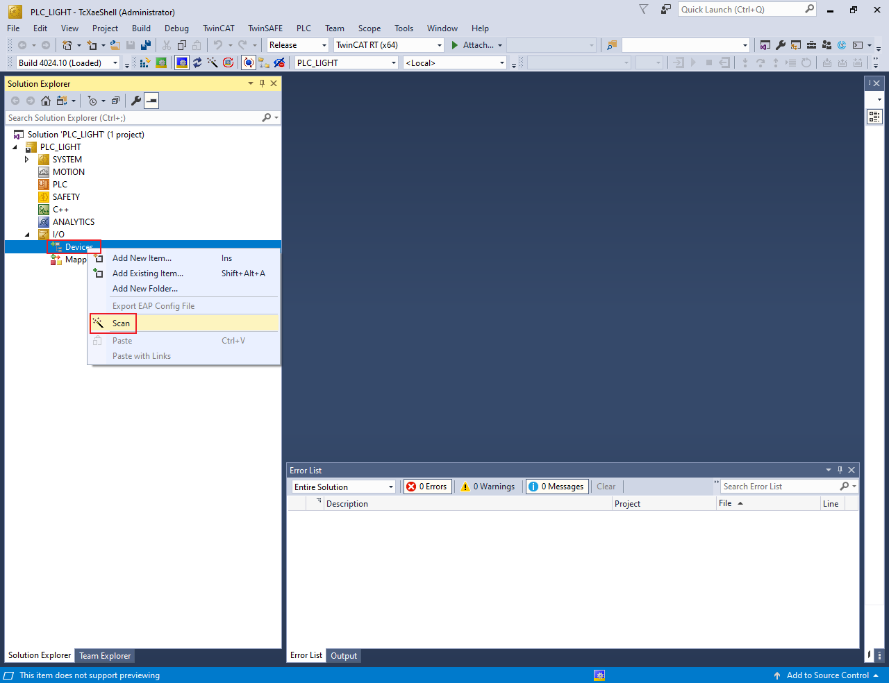
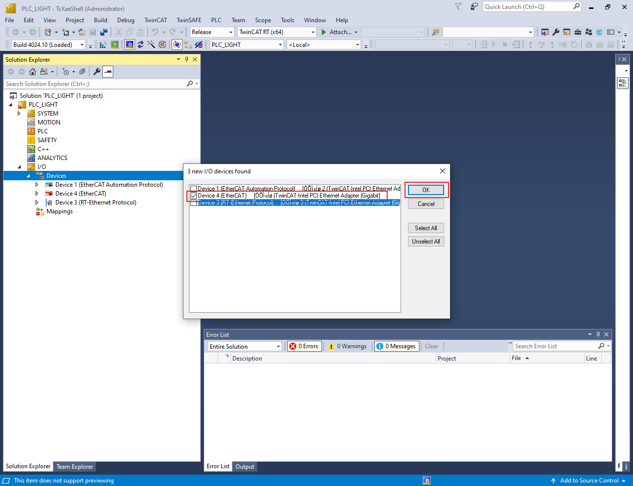
The scanned devices appear in the I/O devices found dialog box.
Select the network interface connected with the MIMXRT1180-EVK board.
Click OK.
Update the ESI file to E2PROM
Note: The E2PROM must be updated if the servo motor example is set up first time on the MIMXRT1180-EVK.
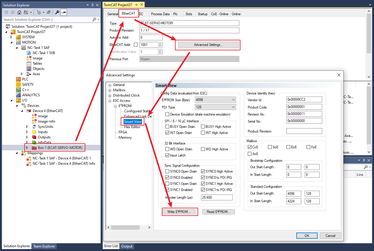
Under Device4, double-click Box 1 (ECAT-SERVO-MOTOR).The TwinCAT Project dialog box appears.
Click the EtherCAT tab.
Click the Advanced Settings button.
The Advanced Settings dialog box appears.
From the left pane of the Advanced Settings dialog box, select ESC Access > Smart View.
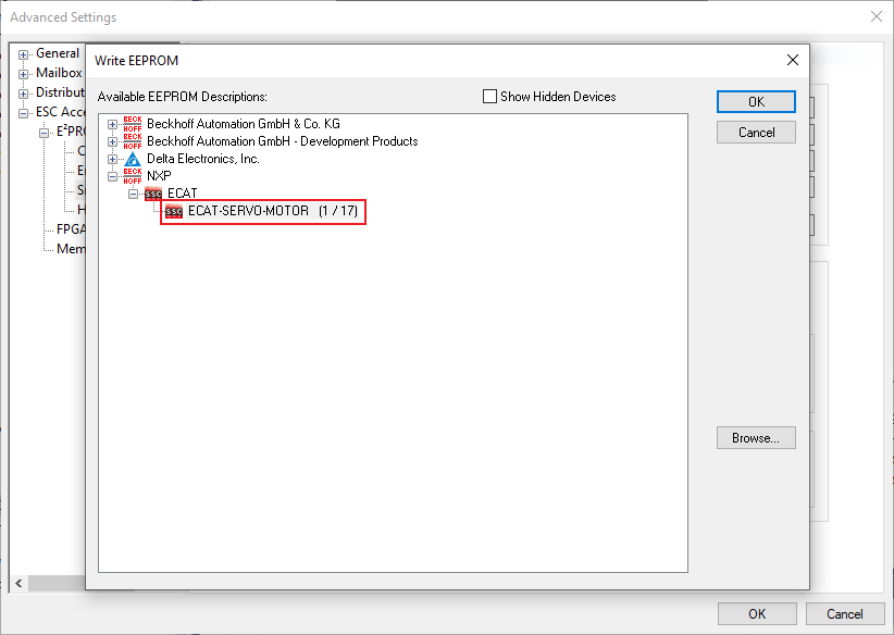
Click the Write E2PROM button.
From the available EEPROM list, select NXP > ECAT > ECAT-SERVO-MOTOR.
Click OK.
Note: Delete Device4, rescan, and add Device4 after Write E2PROM success.
Configure the subdevice
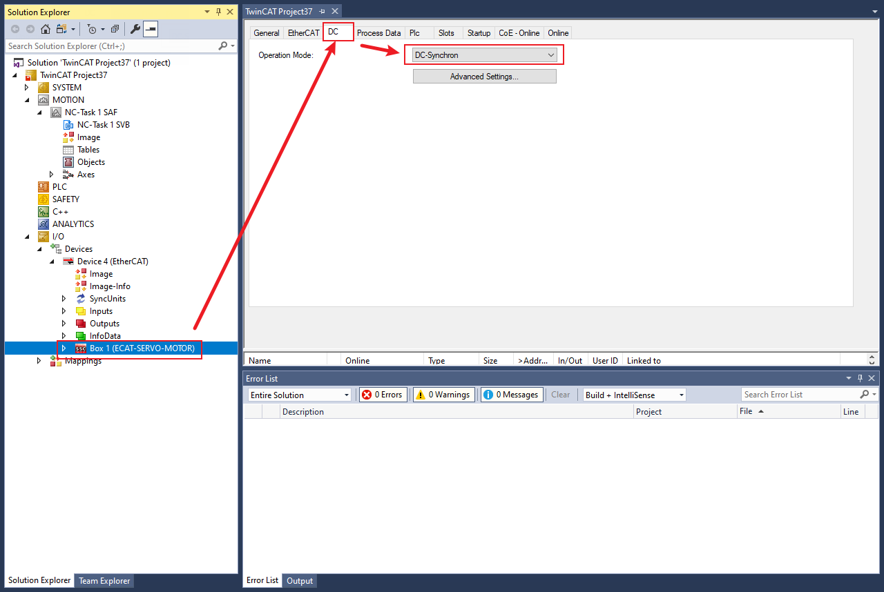
Click Box 1(ECAT-SERVO-MOTOR).
Click the DC tab.
From the Operation Mode field, select the DC-Synchron option.
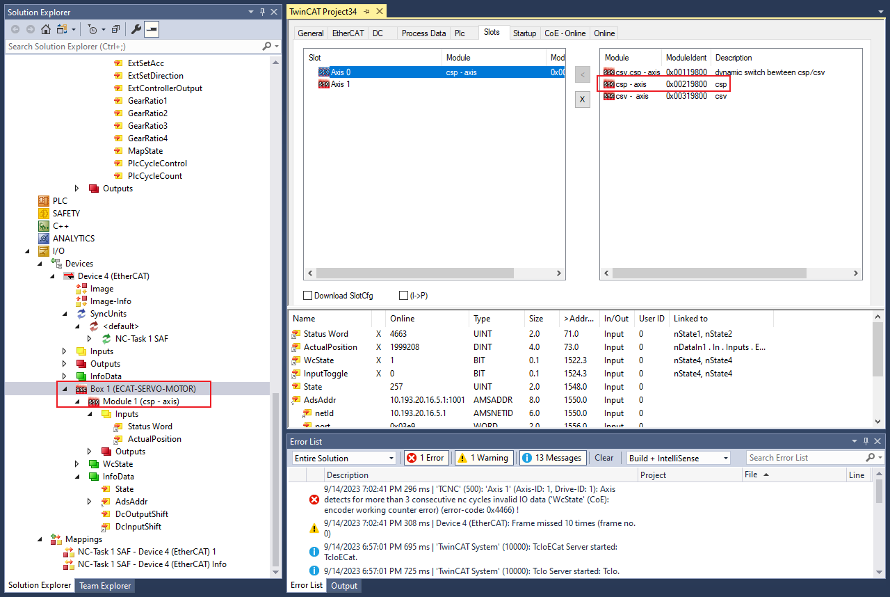
Select the csp mode
Click Box 1(ECAT-SERVO-MOTOR).
Click the Slots tab.
Select Axis 0’ > ‘x’.
Click Axis 0’ > ‘csp - axis’ > ‘<’ to select the csp mode.
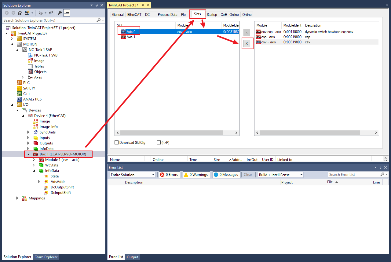
The results are shown in Figure 9.
Add new Axes
Right-click MOTION and click Add New Item.
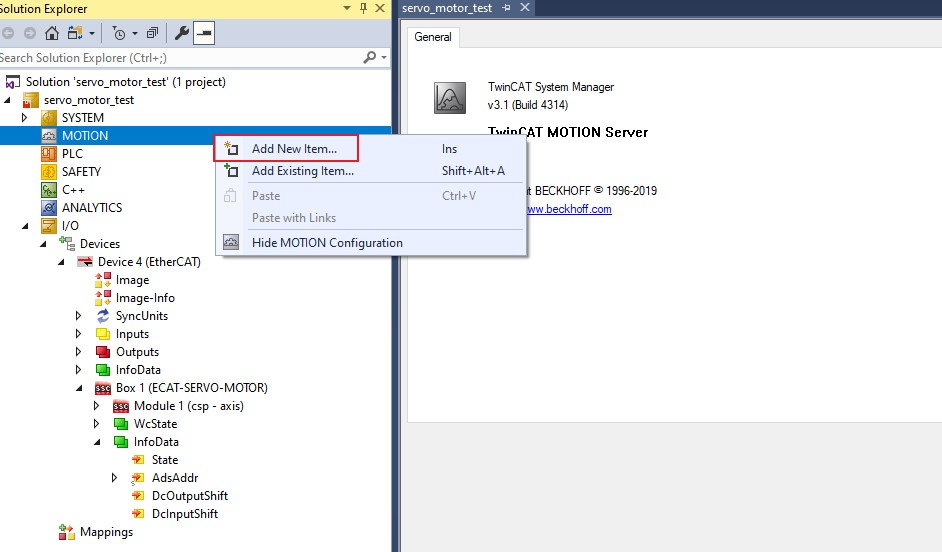
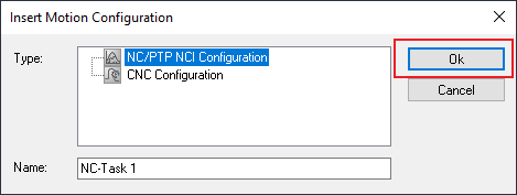
The Insert Motion Configuration dialog box appears.
Select NC/PTP NCI Configuration.
Click OK.
Right-click Axes and click Add New Item > OK.
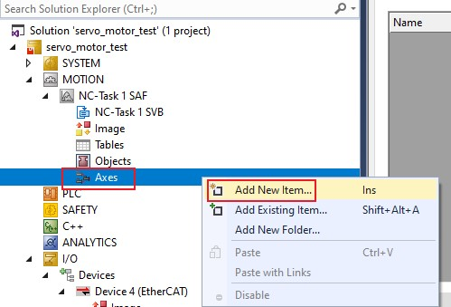
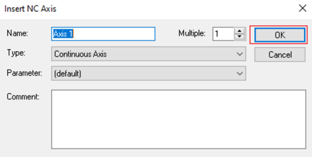
The Insert NC Axis dialog box appears.
Provide the name in the Insert NC Axis text box.
Click OK.
Link I/O
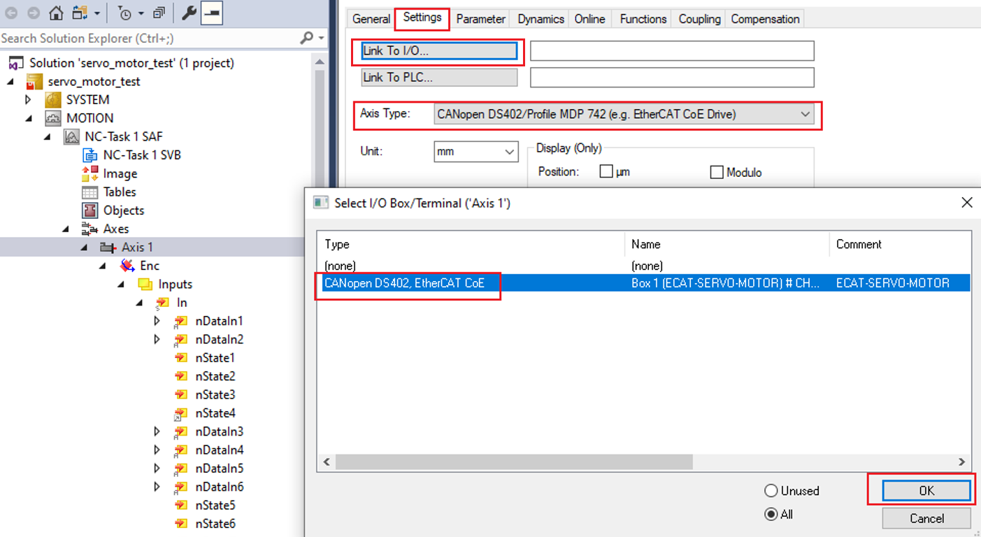
Select Axes > Axis1 from the Solution Explorer,
Click the Settings tab.
Select Link To I/O > CANopen DS402, EtherCAT CoE.
Click OK.
Configure Enc.
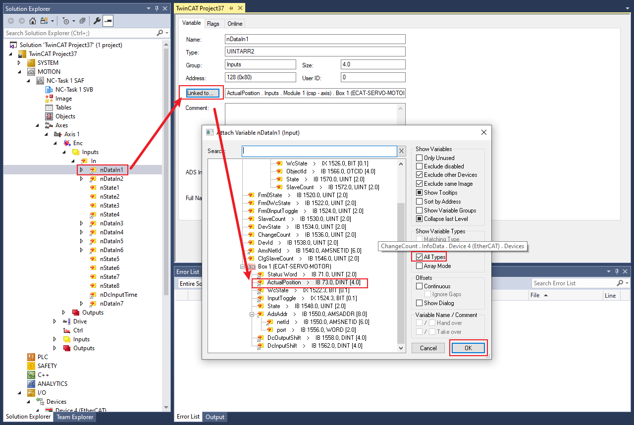
Select Axes > Axis1 > Enc > Inputs > In > nDataIn1 from the Solution Explorer.
The TwinCAT Project dialog box appears.
Click the > Linked to button.
The Attached Variable nDataIn1 (Input) dialog box appears.
Select Box1(ECAT-SERVO-MOTOR) > ActualPosition.
Select All Types checkbox on the right to display all variables.
Click OK.
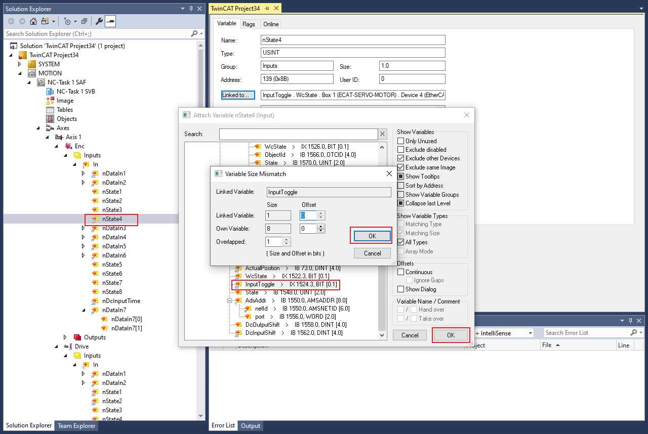
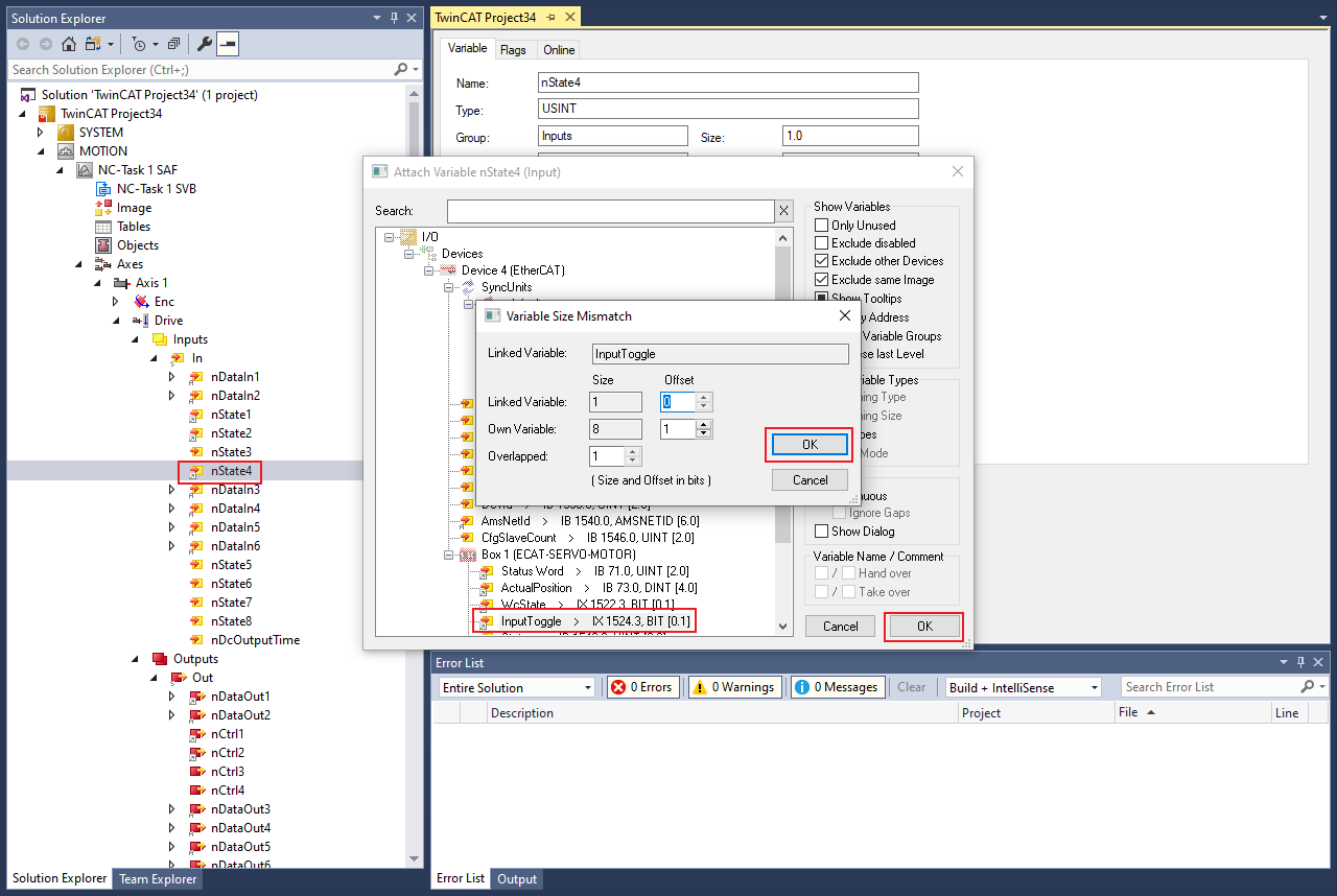
Select Axis1 > Enc >Inputs > In > nState4 > Linked to from the Solution Explorer to link InputToggle.
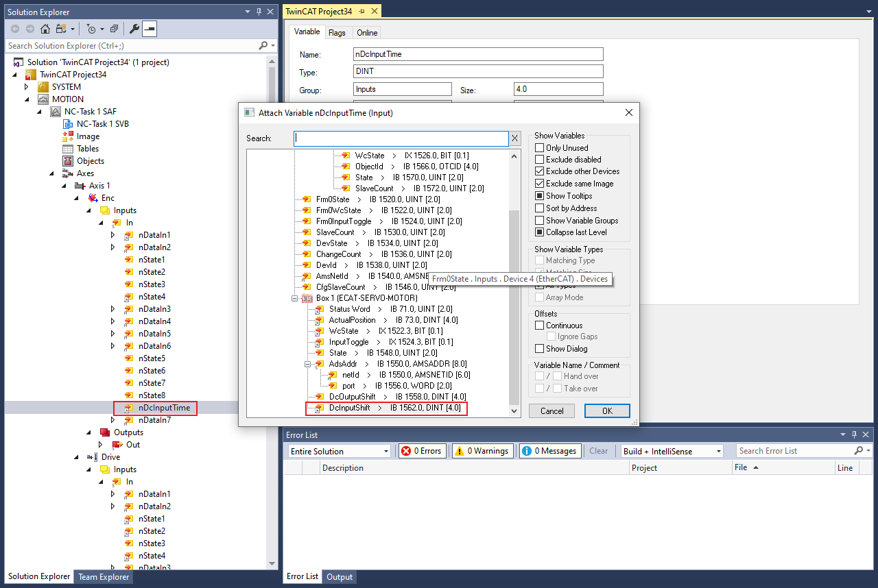
Select Axes > Axis1 > Enc > Inputs > In > nDcInputTime > Linked to to link DcInputShift.
Configure scaling factor
The encoder density of Tecknic2311P motor is 8,000 counts/rev. Tp configure Scaling Factor 1/8000; convert pulse counters to mm using below formula:
Target position(mm) = Motor revolutions(counts) * Scaling Factor
Select Axes > Axis1 > Enc from the Solution Explorer.
The TwinCAT Project dialog box appears.
Click the Parameter tab.
Set Scaling Factor Numerator to
1.Set Scaling Factor Denominator to
8000.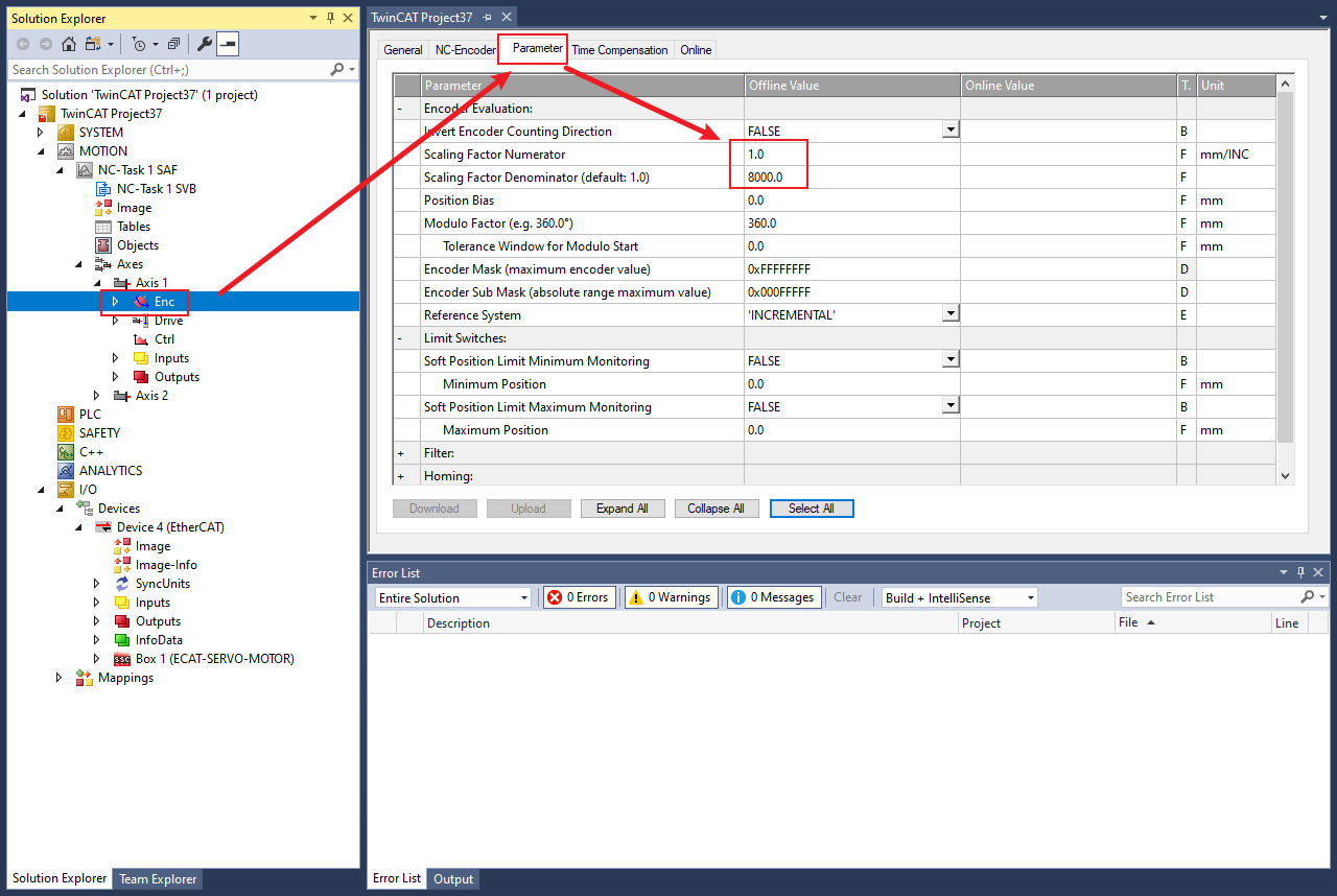
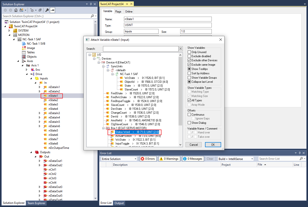
Configure drive
Select Axes > Axis1 > Drive > Inputs > In > nState1 from the Solution Explorer.
The TwinCAT Project dialog box appears.
Click the Linked to button.
The Attached Variable nState1 (Input) dialog box appears.
Select Box1(ECAT-SERVO-MOTOR) > Status Word Linked to link StatusWord.
Click OK.
Click OK to link
StatusWord.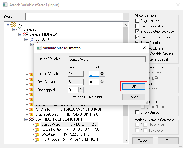
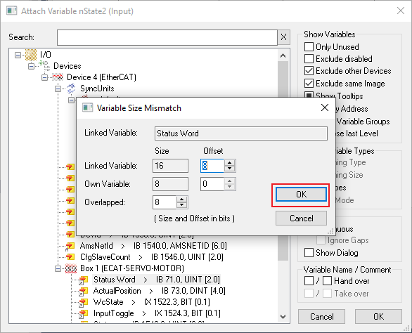
Click Axes > Axis1 > Drive > Inputs > In > nState2 > Linked to to link
StatusWord.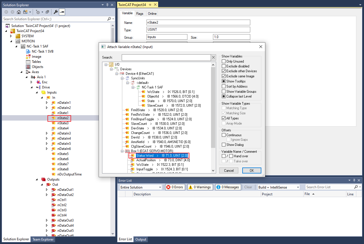
Click Axes > Axis1 > Drive > Inputs > In > nState4 > Linked to to link WcState.
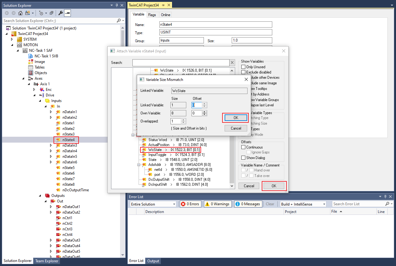
Click OK.
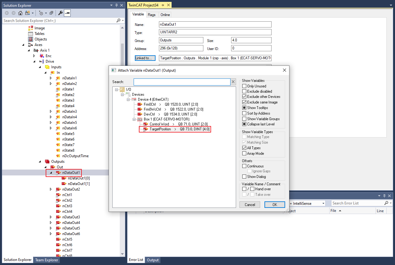
Click Axes > Axis1 > Drive > Outputs > Out > nDataOut1 > Linked to to link TargetPosition.
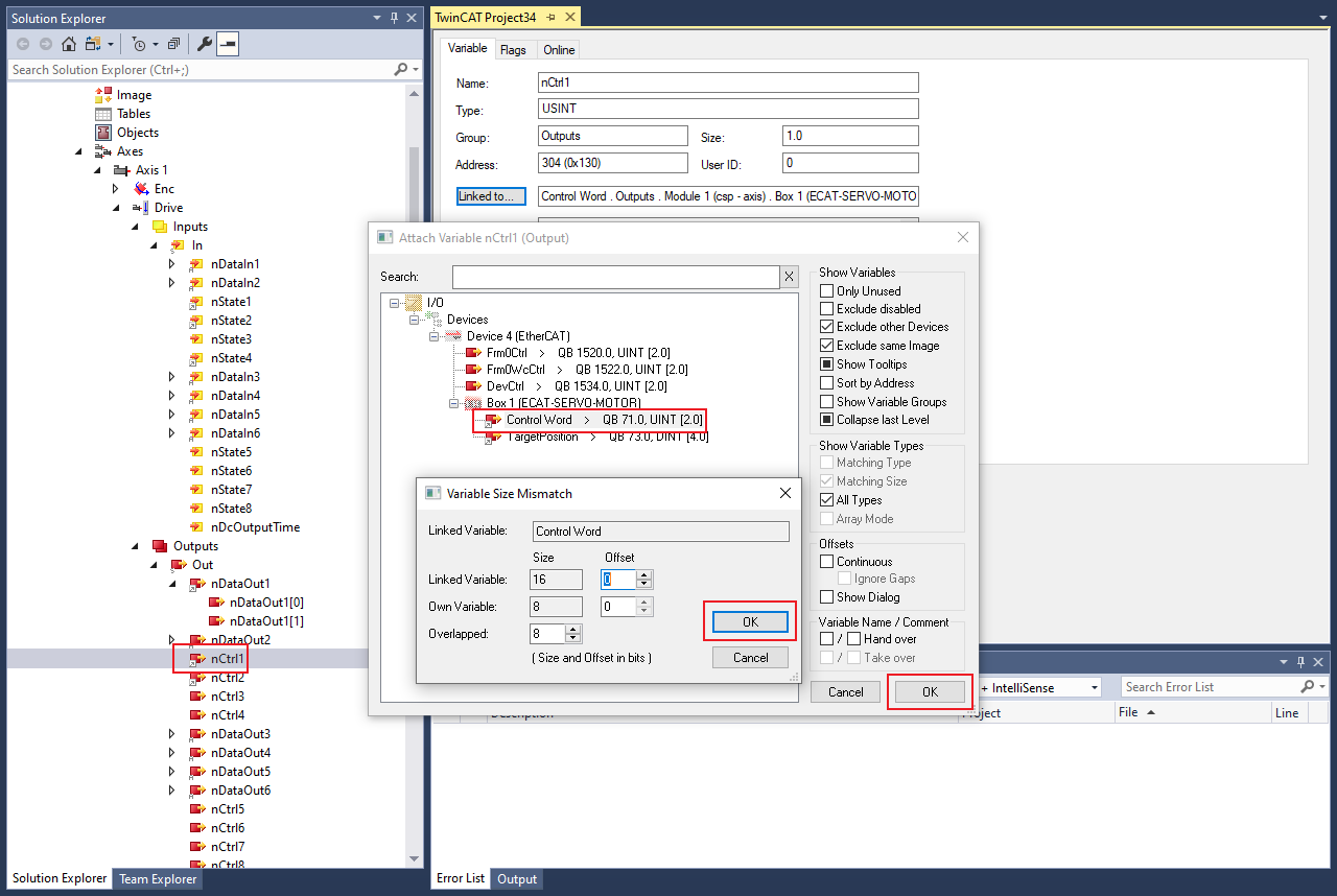
Click Axes > Axis1 > Drive > Outputs > Out > nCtrl1 > Linked to to link ControlWord.
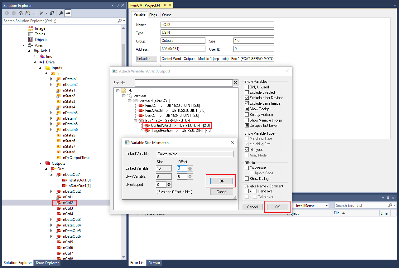
Click Axes > Axis1 > Drive > Outputs > Out > nCtrl2 > Linked to to link ControlWord.
Stop position lag monitoring
Click Axes > Axis1 > Parameter > Monitoring > Position Lag Monitoring to choose
FALSE.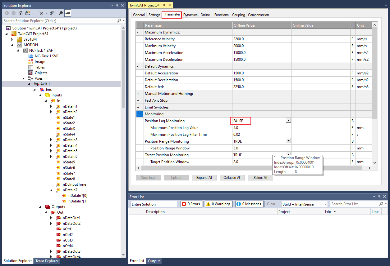
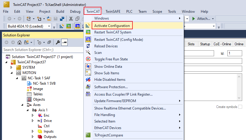
Start to run motor
Activate the configuration by clicking TwinCAT > Activate Configuration.
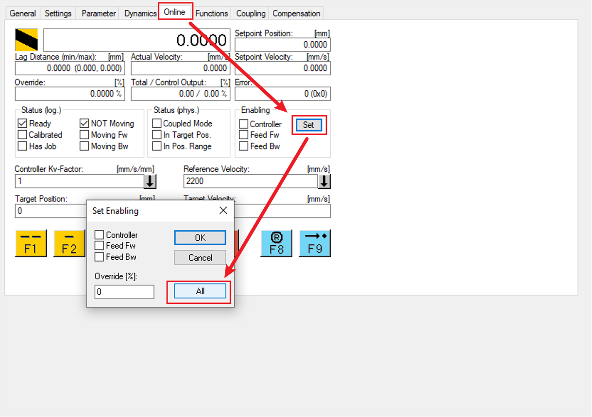
Click Axes > Axis1.
Click the Online tab.
Click Set.
Set enabling and click All.
Set Target Position and click the F5 button. The motor will run to the target position.
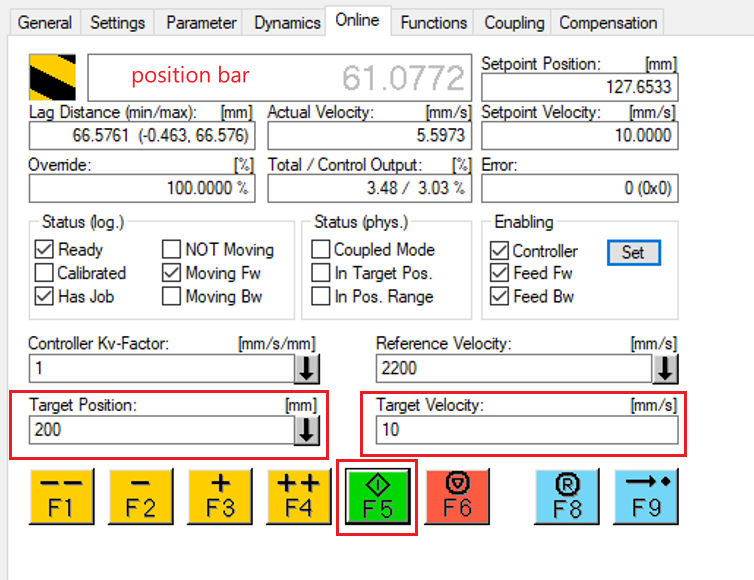
Note: If the motor does not run and the position bar is gray, follow the following steps.
Click Device 4 > Box 1 > WcState > WcState > Clear Link(s).
Click Device 4 > Box 1 > WcState > InputToggle > Clear Link(s).
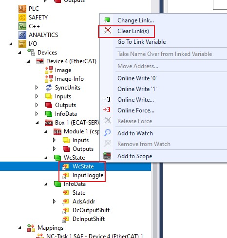
Repeat step Start to run motor..