Connectivity Test CLI
CLI initialization and description
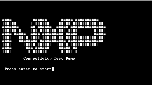
The figure below shows how the Command Line Interface (CLI) menu of the 812.15.4 Connectivity Test application appears at start-up.
Press “Enter” on the message prompt. The full CLI menu is displayed as shown in the figure below.
Connectivity Test Demo CLI
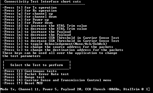
The CLI is divided into three main categories:
Shortcuts: This category provides configuration options that can be used in the tests performed. Shortcuts can be used within any accessed test menu to change the test parameters.
Tests: This category provides the test that can be performed. Each test category numbered from 1 to 4 contains additional options.
Device state: This category indicates the current state of the device. The device state can be modified according to user preference by using the shortcut keys available by the CLI. Device state is displayed within any test menu and is refreshed every time a shortcut command is issued. Device state is not shown when tests are in progress.
Parent topic:Connectivity Test CLI
CLI shortcut command description
Commands from this section are used for configuring the device. All the shortcut commands modifications, except **[x]**and [c], are displayed in the device state.
Shortcut commands cover the following configuration settings:
Device operation mode:
[t]: configures the device in transmitter mode
[r]: configures the device in receiver mode
Channel settings:
Channel number range between [11-26], default value = 11
[q]:increments channel number
[w]: decrements channel number
Output power settings:
Output power range between [0-32], default value = 5
[a]: increments output power
[s]: decrements output power
Crystal trim value settings:
XTAL trim range between [0-127], default value = 0
[d]: increases XTAL trim value
[f]: decreases XTAL trim value
Data payload length settings:
[n]: increases the data payload length
[m]: decreases the data payload length
CCA threshold settings:
CCA Threshold range between [0-110], default value=80
[k]: increases CCA Threshold in Carrier Sense Test
[l]: decreases CCA Threshold in Carrier Sense Test
Packet acknowledgment settings:
Default value = NoAck.
[z]: sets Acknowledgement requirement (NoAck/Ack/EnhancedAck).
Packet source/address settings:
Source address default value = 0xBEAD
Destination address default value = 0xFFFF
[x]: sets source address for packets
[c]: sets destination address for packets
Parent topic:Connectivity Test CLI
CLI test description
Four major test categories are exposed through Connectivity Test Application:
Continuous tests
Packet Error Rate Test
Range Test
Carrier Sense and Transmission Control
Packet Error Rate (PER) menu
The Packet Error Rate (PER) test mode is used to measure the sensitivity of the radio based on packet reception. The content of this menu is strictly related to the operation mode of the device.
PER test can be performed in three different modes:
Transmission without expected acknowledgement.
Transmission with expected acknowledgement.
Transmission with expected enhanced acknowledgement.
Steps to perform a PER test
The steps to perform a PER test procedure are as follows:
Set the source and destination address of the transmitter device. For example,
source=0xaaaa,destination=0xbbb. (Any other address can be chosen instead.) See the figure below.
PER Test: Set source and destination addresses on TX side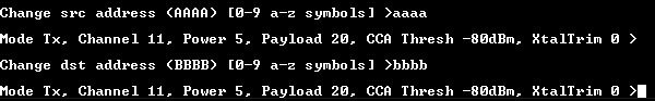
Set the source and destination address of the receiver device. For example,
source=0xbbbb,destination=0xaaaa(Any other addresses can be chosen instead). See the figure below.
PER Test: Set destination and destination addresses on RX side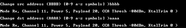
Set the receiver device to run.
Set the transmitter device to run.
Parent topic:Packet Error Rate (PER) menu
Packet error rate when the device is set as transceiver
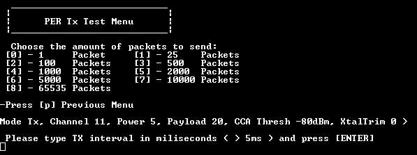
When the device is set to Transmitter mode, it prompts the user to indicate the following:
The number of packets that should be transmitted during the test.
The transmission interval between two consecutive packets.
See the figure below.
Configuring PER for TX device with no ACK
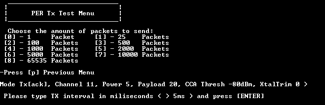
If the acknowledgment setting has not been previously defined, users can decide whether acknowledgment should be present or not.
The type of acknowledgments that can be used by issuing shortcut commands can also be set. See the figure below.
Configuring PER for TX device with ACK
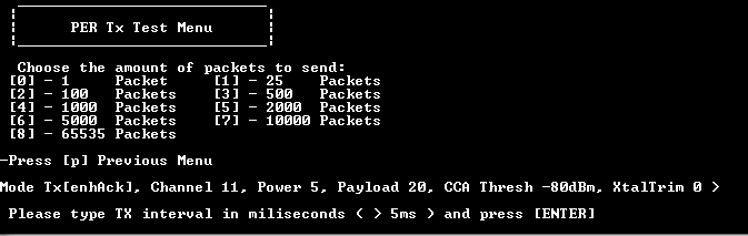
See the figure below.
Configuring PER for TX device with Enhanced ACK
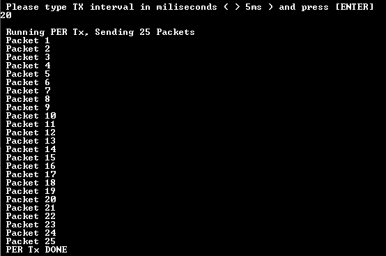
With everything being set, the device starts transmitting the packets over the air as shown in the figure below.
Running PER on TX side
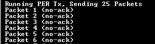
The packet or sequence of packets that have not been acknowledged are indicated on the transmitter CLI. This is applicable for transmissions with acknowledgement or enhanced acknowledgment set, if the receiver device does not send an acknowledgment as required. See the figure below.
Example of not acknowledged packets
Parent topic:Packet Error Rate (PER) menu
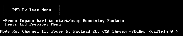
Packet error rate menu when the device is set as receiver
When the device is set to receiver mode, the user is only asked to start or stop the receiving sequence as shown in the figure below.
PER menu interface for RX device
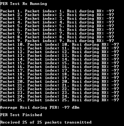
After the receiving sequence begins, incoming packages with destination address set to device’s destination address are shown in the figure below.
Running PER on RX side
Parent topic:Packet Error Rate (PER) menu
Parent topic:CLI test description
Range Test menu
This is a simple and quick test in which data packets are exchanged between two devices.
On the transmitter side, the device initiates the data transfer and expects to receive a packet containing the same data payload. An average RSSI calculation is performed based on the incoming packet’s RSSI and the number of sent packets. If the receiving packet does not contain the same data payload, RSSI calculation is not performed, and a ‘packet dropped’ message is shown in CLI.
On the receiver side, the device sends back the message to originator.
Range tests can be performed in three different modes:
Transmission without expected Acknowledgment.
Transmission with expected Acknowledgment.
Transmission with expected Enhanced Acknowledgment
Steps to perform a Range Test procedure
The steps to perform a Range Test procedure are as follows:
Set the source and destination address of the transmitter device:
source=0xaaaa,destination=0xbbb. (Any other addresses can be chosen). See the figure below.
Range Test: Set the source and destination addresses on TX sideSet the source and destination address of the receiver device.
For example,
source=0xbbbb,destination=0xaaaa. (Any other addresses can be chosen). See the figure below.
Range Test: Set the source and destination addresses on RX sideSet the receiver device to run as shown in the figure below.
Range Test: Set the RX device to run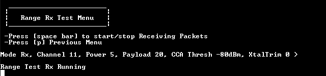
Set the transmitter device to run.
TX device CLI messages are shown in the figures below.
Range Test: TX device CLI messages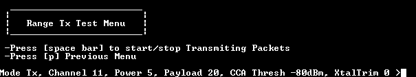 TX device CLI messages
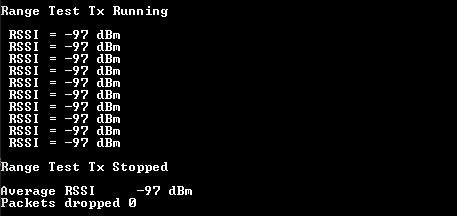
Receiver device CLI messages are as shown in the figure below.
Range Test: RX device CLI messages
Parent topic:Range Test menu
Parent topic:CLI test description
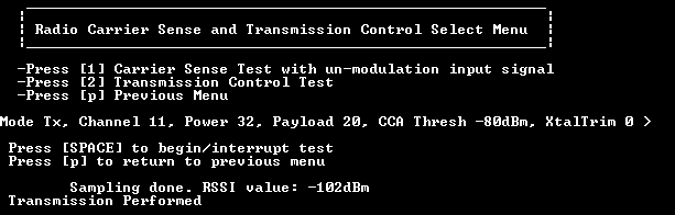
Carrier Sense and Transmission Control Select menu
Carrier Sense Test with unmodulated input signal
This test performs a “manual” Clear Channel Assessment procedure. First, an energy request procedure is done to obtain the RSSI on the specified channel. Then, the obtained RSSI is compared against CCA threshold value, which can be manually set by issuing shortcut commands **[l]**and [k].
If the obtained RSSI value for the specified channel is greater than the CCA threshold value, then the channel is considered busy, no transmission is issued on that channel and another energy detect request is started. This is shown in the below figure.
Carrier Sense Test when RSSI is greater than CCA Threshold
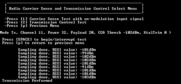
However, if the obtained RSSI value for the specified channel is lower than the CCA Threshold value, then the channel is considered as Idle. It indicates that a transmission has occurred and therefore, the test ends. This is shown in in the below figure.
Carrier Sense Test when RSSI is lower than CCA Threshold
Parent topic:Carrier Sense and Transmission Control Select menu
Transmission Control test
The Transmission Control test performs data transmissions over the air using user-specified options.
The data payload is composed from a predefined data buffer that copies as many bytes as the ‘device state payload data length setting’ indicates.
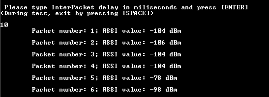
Before any transmission, the test performs an energy detect procedure to obtain the RSSI value of the specified channel. This value is displayed on the side of a message that indicates a message has been sent over the air.
Steps to perform a Transmission Control Test
The figure below illustrates the Transmission Control Test menu.
Transmission Control Test menu
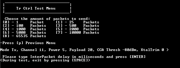
The process to conduct the Transmission Control Test is as follows:
Select the number of packets to be sent.
Specify the inter-packet delay. (Transmission delay between two consecutive packets).
The figure shows this process.
Transmission Control Test execution
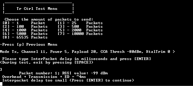
This test also calculates an approximation of time needed to perform the Overhead + Transmission + Energy Detect procedure.
If the inter-packet delay has a value lower than the estimation previously calculated, a corresponding message is shown, and the test finishes the execution as shown in the figure below.
Transmission Control Test – Inter-Packet delay error
Parent topic:Transmission Control test
Parent topic:Carrier Sense and Transmission Control Select menu
Parent topic:CLI test description
Parent topic:Connectivity Test CLI