Bluetooth LE stack and demo applications
ANCS/AMS client (ancs_c)
This section describes the implemented profiles, services, user interactions, and testing methods for the ANCS and AMS Client application.
Implemented profile and services
The ANCS/AMS Client application implements both an ANCS and an AMS Client for the custom ANCS Service and AMS Service available on iOS mobile devices.
Check the documentation available on the iOS website for details about the ANCS or AMS services, their characteristics, and supported features.
The demo application acts as a GAP Peripheral that advertises a service solicitation for the custom ANCS Service, followed by a solicitation to the AMS Service. It also acts as a GATT Client once connected to a device that offers the ANCS/AMS Service. The application offers some services such as the role of GATT Server.
Once connected to a mobile device offering the ANCS/AMS Service, the application displays information about ANCS Notifications received from that device. This information is followed by the AMS track information (Artist, Album, Title, Duration in seconds). The application also displays the possible remote commands that the device state allows (such as Play, Pause, VolumeUp, VolumeDown). The notifications are received via ATT Notifications, for which the ANCS Client must register on the peer ANCS Server. The same must be done for the AMS server. It initially configures the information that it wants to be notified about. The application also retrieves and displays additional information about the received ANCS notifications. For this purpose, it writes commands to specified characteristics on the ANCS/AMS Server and receives responses via ATT Notifications from other characteristics. All information is displayed to the user using a shell available over a serial communications interface.
Accessing the ANCS Service and AMS Service requires Bluetooth LE security to be enabled.
Parent topic:ANCS/AMS client (ancs_c)
Supported platforms
The ANCS/AMS Client application is supported on the following platform:
KW45B41Z-EVK
K32W148-EVK
FRDM-MCXW71
MCX-W71-EVK
KW47-EVK
FRDM-MCXW72
MCX-W72-EVK
Parent topic:ANCS/AMS client (ancs_c)
User interface
After flashing the board, the device is in idle mode (all LEDs flashing). To start advertising, press the ADVSW button. When in GAP Discoverable Mode, CONNLED is flashing. When the ANCS/AMS Server (Gap Central) connects to the ANCS/AMS Client (GAP Peripheral), CONNLED turns solid. To disconnect, hold the ADVSW for 2-3 seconds. The ANCS/AMS Client then re-enters the advertising state.
For displaying operating information and ANCS Notifications (AMS information and commands), the demo application uses a shell exposed via a serial communication interface.
Parent topic:ANCS/AMS client (ancs_c)
Usage
The ANCS/AMS Client demo application is designed to work with a peer mobile device that exposes the ANCS and AMS service. Also, a serial terminal application is required for displaying ANCS Notifications information and AMS commands and information.
Open a serial terminal application on the PC and connect it to the serial port corresponding to the board on which the ANCS/AMS Client runs. See the details in Testing devices, “User Interface”. A start screen is displayed immediately after the board is reset. All LEDs must be flashing as shown in the figure below.
Start screen for ANCS/AMS Client demo application
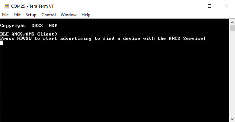
Press the ADVSW button to start advertising. This instruction is also displayed in the serial terminal as shown in the figure above.
The peer device starts scanning for Bluetooth LE devices and connects to the ANCS/AMS Client device that is advertising.
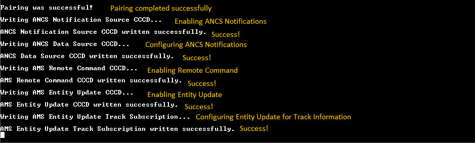
Once connected to a peer, the application looks for the ANCS Service and AMS Service and their characteristics. If they are found, the ANCS Client tries to register for receiving notifications and AMS for the tracking data and commands. See Figure.
If any security-related ATT errors are encountered, then the application automatically performs Pairing and Bonding and retries the failed ATT operations. Depending on the negotiated pairing method, user interaction might be needed to complete the Pairing. Follow the onscreen instructions provided by both the ANCS/AMS Client and the mobile device. If the ANCS/AMS Client generates a passkey, then the default 999999 passkey is used. See the figure below that shows a ‘Pairing is successful’ message.
Pairing is successful message
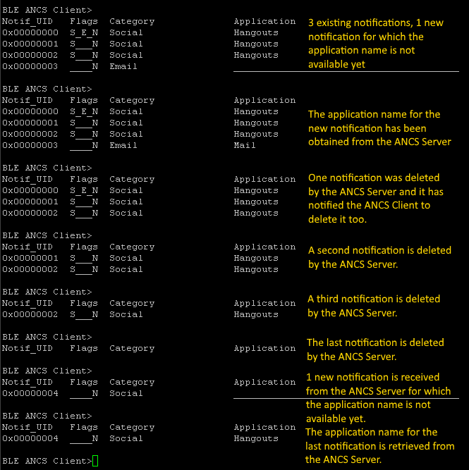
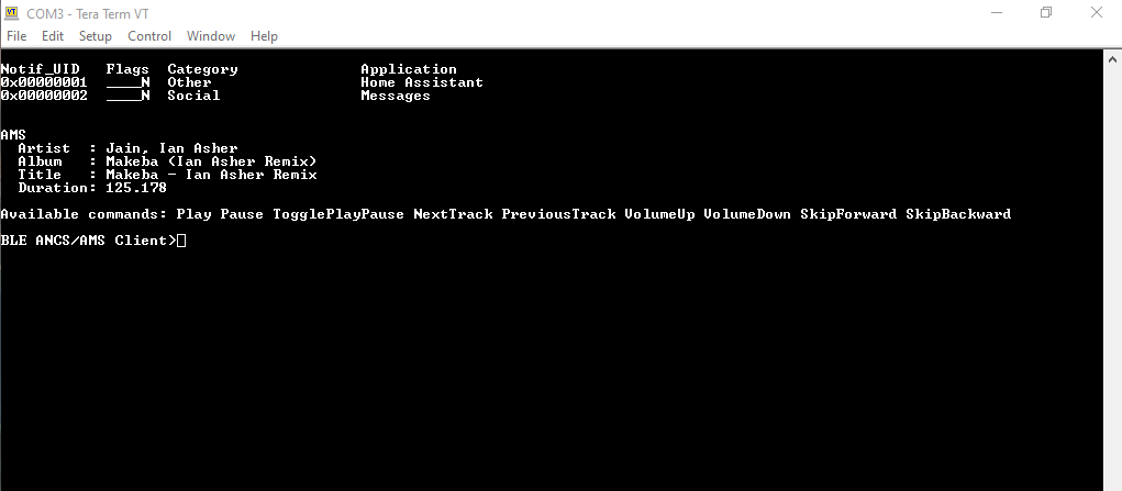
After bidirectional communication is established via GATT, the ANCS/AMS Client starts displaying ANCS Notifications information as shown in the figure below.
ANCS Notifications
The combination of the two services (ANCS and AMS) is shown in the two figures below.
If no media is playing and no player is active, the serial interface looks as shown in the figure below.
AMS no active player
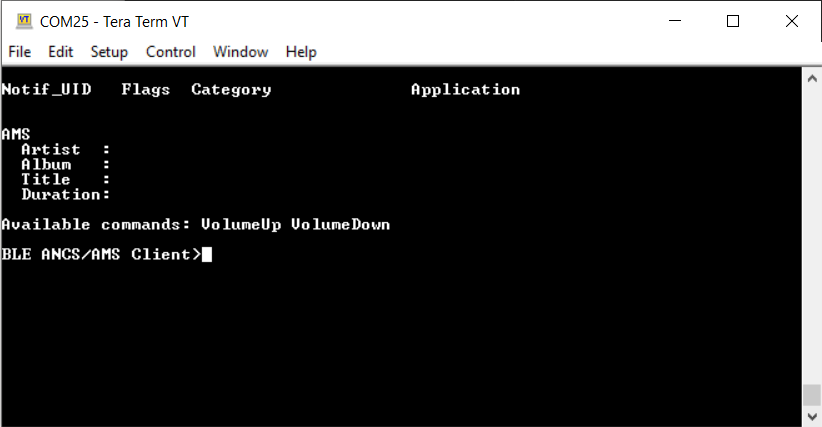
When media is playing, a player is active and the state must look similar to the figure below.
AMS with player active
Parent topic:ANCS/AMS client (ancs_c)
Parent topic:Bluetooth LE stack and demo applications
Beacon
This section presents the user interactions and testing methods for the Beacon application.
Advertising data
The beacons are non-connectable advertising packets that are sent on the three advertising channels. The latter contains the following fields.
Company Identifier (2 bytes): 0x0025 (NXP ID as defined by the Bluetooth SIG).
Beacon Identifier (1 byte): 0xBC (Allows identifying an NXP Beacon alongside with Company Identifier).
UUID (16 bytes): Beacon sensor unique identifier.
A (2 bytes): Beacon application data.
B (2 bytes): Beacon application data.
C (2 bytes): Beacon application data.
RSSI at 1m (1 byte): Allows distance-based applications.
By default, the UUID value is a random value based on the unique identifier of the board.
Parent topic:Beacon
Supported platforms
The following platforms support the Beacon application:
KW45B41Z-EVK
K32W148-EVK
FRDM-MCXW71
MCX-W71-EVK
KW47-EVK
FRDM-MCXW72
MCX-W72-EVK
Parent topic:Beacon
User interface
After flashing the beacon, the sensor is put in deep sleep (all LEDs are off). To flash the board in case the beacon is put in Deep-sleep mode, press the ADVSW or RESET button. After this step, any attached debugger loses its connection. The default configuration of the application enables low power, which disables LED support. The user can manually change the configuration and enable LED support, otherwise all subsequent LED behavior references are ignored.
By default, the application uses extended advertising. However, it can be configured to use legacy advertising by setting the gBeaconAE_c define to 0. In the legacy configuration, the first press of the advertising switch starts the legacy advertising and the second press stops it.
Parent topic:Beacon
Usage
The beacon can be tested with any Bluetooth® Smart Ready products available on the market. The IoT Toolbox can also be used to showcase the profile functionality, as shown in the figure IoT Toolbox Beacon Demo below.
![]()
Parent topic:Beacon
Beacon usage with extended advertising
To use the Beacon application with the advertising extensions capabilities, the gBeaconAE_c define option must be set to 1. Doing this enables the usage of extended advertising and periodic advertising. The application cycles between these modes are in the following manner:
The first ADVSW press starts legacy advertising, CONNLED turns solid.
The second ADVSW press stops legacy advertising and starts extended advertising, CONNLED turns off, EXTADVLED turns solid.
The third ADVSW press stops extended advertising carrying data and then starts extended advertising without data and periodic advertising, EXTADVLED starts flashing.
The fourth ADVSW press stops periodic advertising and extended advertising without data and starts legacy advertising and extended advertising, both CONNLED and EXTADVLED turn solid.
The fifth ADVSW press stops them all, both CONNLED and EXTADVLED turn off.
Not all smartphones support extended advertising, hence a different method to view the AE beacon is to use the ble_shell application. In order to do this, perform the following steps:
Flash a board with the beacon application, as described above.
Flash a board with the ble_shell application, as described in Bluetooth LE Shell and connect to it using a serial port.
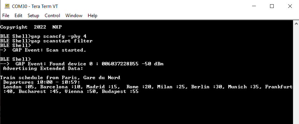
Press the ADVSW button two times on the beacon to start extended advertising on the coded PHY.
To view the advertising data, enter the following commands in the shell terminal to set the scanning PHY to coded and start scanning. See the figure below.
|
To start the periodic advertising, press ADVSW button again on the beacon.
To sync with the beacon, issue the following commands on the shell terminal as shown in the figure below.
|
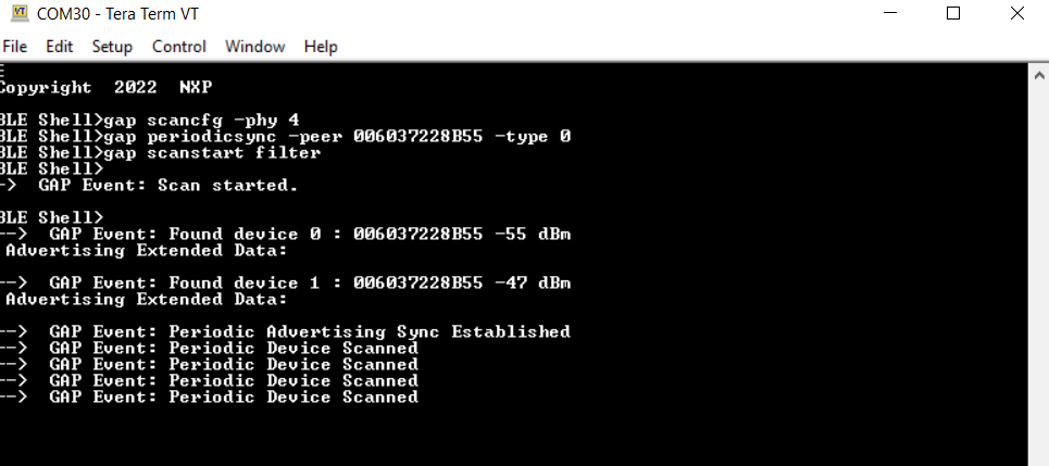
The peer parameter of the
periodicsynccommand is the public address of the beacon.
Extended Advertising with very large data
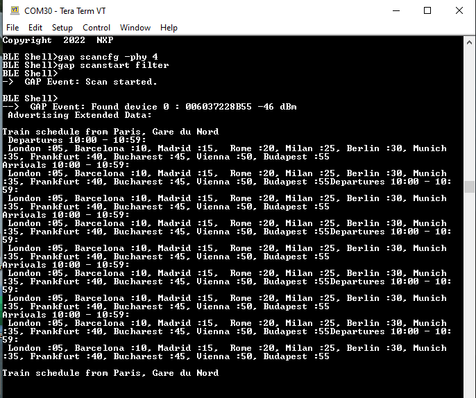
To use very large advertising data for extended advertising, set the gBeaconLargeExtAdvData_c define to 1. The same steps are used to view the data using ble_shell :
Flash a board with the beacon application.
Flash a board with the ble_shell application, as described in Bluetooth LE Shell and connect to it using a serial port.
Press the ADVSW button two times on the beacon to start extended advertising on the coded PHY.
To view the advertising data, enter the following commands in the shell terminal to set the scanning PHY to coded and start scanning. See the figure below.
Parent topic:Beacon
Parent topic:Bluetooth LE stack and demo applications
Bluetooth LE FSCI Black Box
This section describes the functionality, user interactions, and testing methods for the Bluetooth LE FSCI Black Box demo application.
Description
The Bluetooth LE FSCI Black Box demo application gives access to the Bluetooth LE Host Stack via a serial interface using the FSCI protocol. See the FSCI (Framework Serial Communication Interface) manual for the format of the FSCI commands and a full list of supported commands.
The demo can be used with the Test Tool for Connectivity Products. Command Console application can be downloaded from the NXP website or using a custom application that supports the FSCI protocol and commands.
Parent topic:Bluetooth LE FSCI Black Box
Supported platforms
The following platforms support Bluetooth LE FSCI Black Box application:
KW45B41Z-EVK
K32W148-EVK
FRDM-MCXW71
MCX-W71-EVK
KW47-EVK
FRDM-MCXW72
MCX-W72-EVK
Parent topic:Bluetooth LE FSCI Black Box
Usage with Test Tool for connectivity products
The Bluetooth LE FSCI Black Box demo application is designed to be used via serial interface. This can be done using the TEST Tool for Connectivity Products – Command Console application as described below.
Download the demo application onto a supported board.
Connect the board to a USB port of the PC. The UASB COM port drivers must be installed properly and a COM port corresponding to the board should be available.
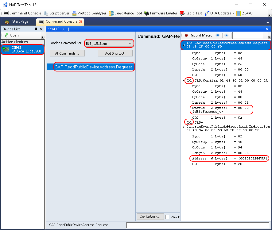
Open the Test Tool application and connect to the serial port corresponding to the board on which the Bluetooth LE FSCI Black Box application runs. See Figure. The serial communication parameters are: baud rate 115200, 8N1, and no flow control.
Select the appropriate Test Tool XML file from the drop-down list for the release being used and send commands to the application. An example is shown in Figure.
Parent topic:Bluetooth LE FSCI Black Box
Parent topic:Bluetooth LE stack and demo applications
EATT Central
This section describes the implemented profiles and services, user interactions, and testing methods for the EATT Central application.
Implemented profiles and services
The EATT Central application implements a GATT server and the following profiles and services:
Generic Attribute Profile
The application behaves as a GAP central node. It searches for an EATT peripheral to connect to. After connecting, it performs service discovery, initiates an EATT connection and configures indications on the peripheral for services A and B. The Central reports the received service data and the steps taken during the setup on a terminal connected to an UART port.
Parent topic:EATT Central
Supported platforms
The EATT Central application is supported on the following platforms:
KW45B41Z-EVK
K32W148-EVK
FRDM-MCXW71
MCX-W71-EVK
KW47-EVK
FRDM-MCXW72
MCX-W72-EVK
Parent topic:EATT Central
User interface
After flashing the board, the central is in Idle mode (all LEDs flashing). To start scanning, press the SCANSW button. After connecting to the peripheral, the CONNLED turns solid. The data information together with the bearer it was received on is sent over UART. To disconnect the node, hold the SCANSW button pressed for 2-3 seconds. The node then restarts scanning.
Parent topic:EATT Central
Usage
The application can be tested using another board flashed with the EATT Central application as described in the EATT Peripheral.
Open a serial port terminal and connect it to board, in the same manner described in Testing devices. The start screen is displayed after the board is reset.
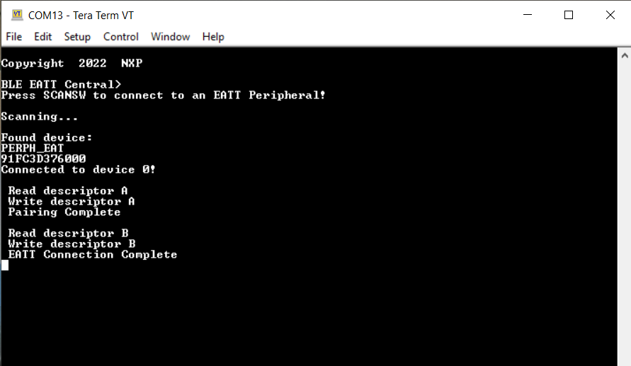
To start scanning for devices, press the SCANSW button on the EATT Central board. To make it enter discoverable mode, perform the same step on the EATT Peripheral board. The host connects with the board after it sees it advertise the service A and service B UUIDs. After connecting, the central performs service discovery, indicates its EATT support to the server by writing the Client Supported Features characteristic, enables indications for services A and B, and then initiates an EATT connection with the server. See the figure below.
Output console on the EATT Central connected with an EATT Peripheral
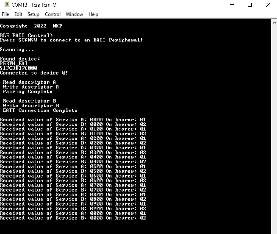
After the EATT connection is complete, the console displays the received data and the bearer on which it was sent, as shown in the figure below.
Output console on EATT Central
Parent topic:EATT Central
Parent topic:Bluetooth LE stack and demo applications
EATT Peripheral
This section describes the implemented profiles and services, user interactions, and testing methods for the EATT Peripheral application.
Implemented profiles and services
The EATT Peripheral application implements a GATT server and the following profiles and services:
Battery Service v1.0
Device Information Service v1.1
Generic Attribute Profile
The Generic Attribute Profile includes the Server Supported Features characteristics, which is used to indicate EATT support to the peer, and the Client Supported Features characteristic, which is used by the peer to indicate its own EATT support.
The application behaves as a GAP peripheral node. It enters GAP General Discoverable Mode and waits for a GAP central node to connect. The application implements two custom services, Service A and Service B. After the EATT connection is completed, the peer must enable indications for the two services to periodically receive profile data over EATT.
Parent topic:EATT Peripheral
Supported platforms
The EATT Peripheral application is supported on the following platforms:
KW45B41Z-EVK
K32W148-EVK
FRDM-MCXW71
MCX-W71-EVK
KW47-EVK
FRDM-MCXW72
MCX-W72-EVK
Parent topic:EATT Peripheral
User interface
After flashing the board, the peripheral is in idle mode (all LEDs flashing). To start advertising, press the ADVSW button. When in GAP Discoverable Mode, CONNLED is flashing. When a central node connects to the peripheral, CONNLED turns solid. The node then waits for an EATT connection request and for the client to configure indications for the two services. The service information is sent over enhanced bearers only. The values indicated are cycled between 0 and 10. To disconnect the node, hold the ADVSW button for 2-3 seconds. The node then re-enters GAP Discoverable Mode and starts advertising.
Parent topic:EATT Peripheral
Usage
The application can be tested using another board flashed with the EATT Central application as described in the EATT Central Section.
Parent topic:EATT Peripheral
Parent topic:Bluetooth LE stack and demo applications
HCI Black Box
This section describes the functionality, user interactions, and testing methods for the Bluetooth LE HCI Black Box demo application.
Description
The Bluetooth LE HCI Black Box demo application gives access to the Bluetooth LE Controller via a serial interface using the HCI protocol over serial interface. Refer to the Bluetooth Specification for the format of HCI commands and events over serial interface and the full list of supported commands and events.
The demo can be used with the Test Tool for Connectivity Products. The Command Console application can be downloaded from the NXP website. Alternatively you can also download it using a custom application that supports the HCI protocol and commands and events over serial interface.
Note: The HCI protocol encapsulation is dependent on the type of interface it is being used on. See the Bluetooth Specification for the HCI message format on each type of supported interface.
For instructions using the Bluetooth LE HCI Black Box with a serial terminal application or the hcitool in Linux, check the article “FRDM-KW40Z Bluetooth LE Controller Usage with the Linux hcitool”.
Parent topic:HCI Black Box
Supported platforms
The following platforms support the HCI Black Box application:
KW45B41Z-EVK
K32W148-EVK
FRDM-MCXW71
MCX-W71-EVK
KW47-EVK
FRDM-MCXW72
MCX-W72-EVK
Parent topic:HCI Black Box
Usage with Test Tool for Connectivity products
The Bluetooth LE HCI Black Box demo application is designed to be used via serial interface. This can be achieved using the TEST Tool for Connectivity Products – Command Console application as described below.
Download the demo application to a supported board.
Connect the board to a USB port of the PC. The UASB COM port drivers must be installed properly and a COM port corresponding to the board should be available.
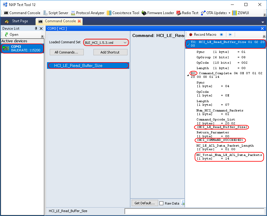
Open the Test Tool application and connect to the serial port corresponding to the board on which the Bluetooth LE HCI Black Box application runs. The serial communication parameters are: baud rate 115200, 8N1, and no flow control. See the figure Test tool command console serial port selection below.

Select the appropriate Test Tool HCI XML file from the drop-down list for the release you are using. Send a few commands to the application. An example is shown in the figure HCI black box command example below.
Parent topic:HCI Black Box
Parent topic:Bluetooth LE stack and demo applications
HID Device (Mouse)
This section describes implemented profiles and services, user interactions, and testing methods for the HID mouse application.
Implemented profiles and services
The HID Device application implements a GATT server and the following profile and services.
HID over GATT Profile v1.0
Human Interface Device Service v1.0
Battery Service v1.0
Device Information Service v1.1
The application behaves as a GAP peripheral node. It enters GAP General Discoverable Mode and waits for a GAP central node to connect. Security on the services and bonding is enabled on this device.
When the GATT client configures notification, the application starts sending HID reports every two seconds with the movement of the MOUSE_STEP. The demo moves the cursor in a square pattern between AXIS_MIN and AXIS_MAX. The report contains 3 bytes, one for button status, one for X axis, and one for Y axis. The report descriptor matches the example in chapter E.10 from the USB Device Class Definition for Human Interface Devices (USB HID Specification), Version 1.11.
Parent topic:HID Device (Mouse)
Supported platforms
The following platforms support the HID Device application:
KW45B41Z-EVK
K32W148-EVK
FRDM-MCXW71
MCX-W71-EVK
KW47-EVK
FRDM-MCXW72
MCX-W72-EVK
Parent topic:HID Device (Mouse)
User interface
After flashing the board, the device enters Idle mode with all LEDs flashing. To start advertising, press the ADVSW button. In GAP Discoverable mode, CONNLED is flashing. When the central node connects to the peripheral, CONNLED turns solid. To disconnect the node, hold the ADVSW pressed for 2-3 seconds. The node then re-enters GAP Discoverable Mode.
Parent topic:HID Device (Mouse)
Usage
The HID mouse can be connected to any Bluetooth Smart Ready products available on the market that supports HID devices or to another supported platform running the HID Host example (setup steps detailed in the HID Host section).
To make the HID mouse visible, press the ADVSW button to start sending advertisements, which causes CONNLED to start flashing. See the figure Enter PIN prompt on Android platform below.
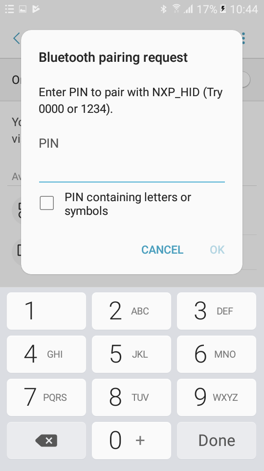
The sensor name “NXP_HID” shows on the device when its scanning is active. A solid CONNLED indicates a successful connection between the 2 devices. When prompted to enter the pin, type the 999999 passkey.
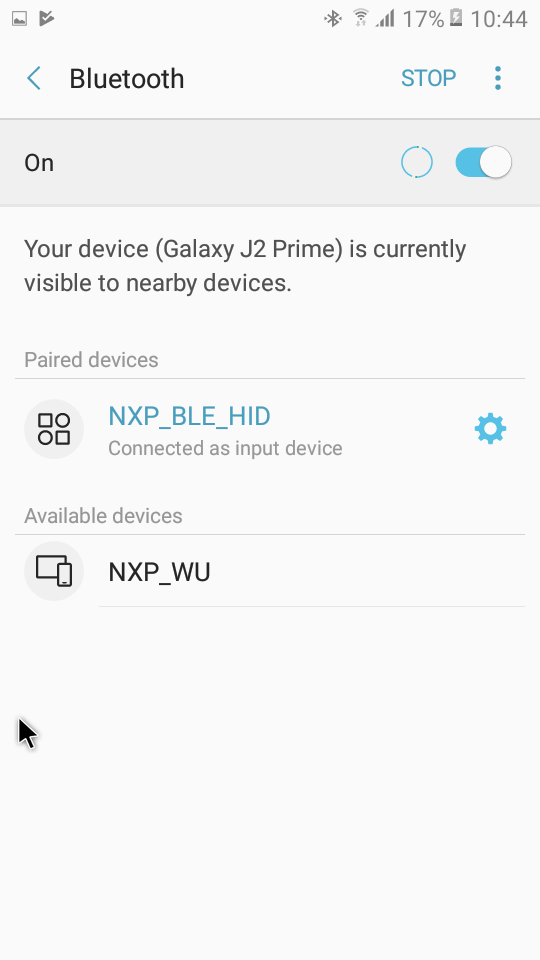
When configured, the HID mouse starts sending HID report, which is configured as explained above, with notifications every 100 milliseconds. The mouse cursor shows a square pattern movement on the screen as shown in the figure HID Mouse detected by Android platform below.
Parent topic:HID Device (Mouse)
Parent topic:Bluetooth LE stack and demo applications
HID Host
This section presents the implemented profiles and services, user interactions, and testing methods for the HID Host application.
Implemented profiles and services
The HID Host application implements a GATT client or server for the following profile and service.
HID over GATT Profile v1.0
Battery Service v1.0
Device Information Service v1.1
The application behaves as a GAP central node. It enters the GAP Limited Discovery Procedure and searches for HID devices to connect to. After connecting with the peripheral, it configures notifications and displays the received HID reports on a terminal connected to the UART port. The application uses pairing with bonding by default. When connected with the HID Device application, it sends the 999999 passcode to the host stack by default.
Parent topic:HID Host
Supported platforms
The following platforms support the HID Host application:
KW45B41Z-EVK
K32W148-EVK
FRDM-MCXW71
MCX-W71-EVK
KW47-EVK
FRDM-MCXW72
MCX-W72-EVK
Parent topic:HID Host
User interface
After flashing the board, the device is in idle mode (all LEDs flashing). To start scanning, press the SCANSW button. When in GAP Limited Discovery Procedure, CONNLED is flashing. When the central node connects to the peripheral, CONNLED turns solid. To disconnect the node, hold the SCANSW button pressed for 2-3 seconds. The node then re-enters GAP Limited Discovery Procedure.
Parent topic:HID Host
Usage
The application is built to work only with the HID Device application presented in HID Device (Mouse). It supports up to 2 peripherals connected at the same time.
Open a serial port terminal and connect it to board, in the same manner described in Testing devices. The start screen is displayed after the board is reset.
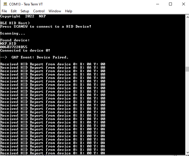
To start scanning for devices, press the SCANSW button on the HID Host board. To make it enter discoverable mode, perform the same step on the HID device board. The host connects with the board after it sees it advertise the HID service, connects to it, and configures report notifications. The device then starts sending HID reports, as shown in Figure.
HID host
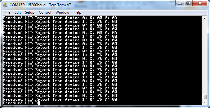
To connect a second HID device, press again the SCANSW button on the HID Host board to start scanning for devices. Do the same on the second HID device board to make it enter discoverable mode. The host connects with the board after it sees it advertise the HID service, connects to it, and configures report notifications. The device then starts sending HID reports. The console displays reports from both devices, as shown in Figure.
Tera Term – Output Console on HID Host with 2 peripherals connected

Parent topic:HID Host
Parent topic:Bluetooth LE stack and demo applications
Low-power temperature sensor and collector
This section describes the implemented profiles and services, user interactions, and testing methods for the temperature sensor application.
Implemented profiles and services
The Temperature Sensor application implements a GATT server, a custom profile and the following services.
Temperature Service (UUID: 01ff0200-ba5e-f4ee-5ca1-eb1e5e4b1ce0)
Battery Service v1.0
Device Information Service v1.1
The application behaves as a GAP peripheral node. It enters GAP General Discoverable Mode and waits for a GAP central node to connect and configure notifications for the temperature value.
The Temperature service is a custom service that implements the Temperature characteristic (UUID: 0x2A6E) with a Characteristic Presentation Format descriptor (UUID: 0x2904), both defined by the Bluetooth SIG.
The Temperature Collector application implements a GATT client or server for the following profile and services.
Temperature Service (UUID: 01ff0200-ba5e-f4ee-5ca1-eb1e5e4b1ce0)
Battery Service v1.0
Device Information Service v1.1
The application behaves as a GAP central node. It enters GAP Limited Discovery Procedure and searches for sensor devices to pair with. After pairing with the peripheral, it configures notifications and displays temperature values on a terminal connected to the UART port.
Both application uses pairing with bonding by default. When connected with the Low-Power Temperature Sensor application, the collector sends the 999999 passcode to the host stack by default.
Parent topic:Low-power temperature sensor and collector
Supported platforms
The Temperature Sensor and Collector applications are supported by the following platforms:
KW45B41Z-EVK
K32W148-EVK
FRDM-MCXW71
MCX-W71-EVK
KW47-EVK
FRDM-MCXW72
MCX-W72-EVK
Parent topic:Low-power temperature sensor and collector
User interface
After flashing the board, both nodes enter Low-power mode. In case the sensor is put in deep sleep, press WAKESW or RESET. To flash the board in case the sensor is put in deep sleep, press either WAKESW or RESET button. By default, the application is configured to be in low power mode, which disables LED support.
The user can manually change this configuration and enable LED support, else all subsequent LED behavior references are ignored and all LEDs are off. The devices disconnect and enter Deep-sleep only if low power is enabled. When the node is awake and communicating, CONNLED is on. To wake up the node, press the WAKESW button.
Parent topic:Low-power temperature sensor and collector
Usage
The setup requires two supported platforms, one for the temperature sensor and one for the temperature collector.
Open a serial port terminal and connect it to the temperature collector board, in the same manner as described in Testing devices. The start screen is displayed after the board is reset. At first the LEDs are off on both devices.
To start advertising on the sensor, press the WAKESW button and CONNLED lights up. The sensor enters into the Deep-sleep mode, which means that the MCU wakes up on any packet from the Link layer, in this case the connect request. If no connection is established in an interval of 30 seconds, the sensor stops advertising and enters into the Deep-sleep mode again. CONNLED turns off.
To start scanning on the collector, press the WAKESW button and CONNLED lights up. The device wakes up, enters into the Deep-sleep mode, scans, and connects to a compatible sensor device. If no connection is established within 30 seconds, the collector stops scanning and enters Deep-sleep mode again. CONNLED turns off.
If the collector connects to a sensor node, it bonds (if no bond was previously made), does service discovery (only the first time it connects with the sensor), and configures notification and waits for notifications from the sensor for 5 seconds. If no data is sent, the node disconnects and re-enters Deep-sleep mode. The sensor exits low power and sends a notification with the value of the temperature read through an ADC from the thermistor, if present, or random generated if not.
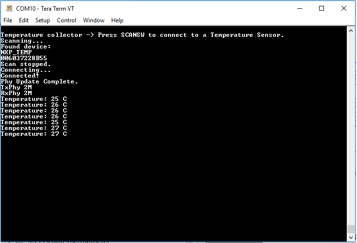
Once the connection is established, the PHY is automatically updated to 2M, if both the sensor and the collector support this feature as shown in the figure below. The PHY update is configurable from the application.
Output Console on Temperature Collector
Subsequent key pressing triggers other notifications for the collector. If no key is pressed in an interval of 5 seconds, the sensor node disconnects and re-enters Deep-sleep mode.
Parent topic:Low-power temperature sensor and collector
Parent topic:Bluetooth LE stack and demo applications
Low-power extended advertising Peripheral and Central
This section describes the implemented profiles and services, user interactions, and testing methods for the adv_ext_peripheral and adv_ext_central applications.
Implemented profile and services
The adv_ext_peripheral application implements a GATT server, a custom profile and the following services.
Temperature Service (UUID: 01ff0200-ba5e-f4ee-5ca1-eb1e5e4b1ce0)
Battery Service v1.0
Device Information Service v1.1
The application behaves as a GAP peripheral node. It enters GAP General Discoverable Mode and waits for a GAP central node to connect and configure notifications for the temperature value.
The Temperature service is a custom service that implements the Temperature characteristic (UUID: 0x2A6E) with a Characteristic Presentation Format descriptor (UUID: 0x2904), both defined by the Bluetooth SIG.
The adv_ext_central application implements a GATT client or server for the following profile and services.
Temperature Service (UUID: 01ff0200-ba5e-f4ee-5ca1-eb1e5e4b1ce0)
Battery Service v1.0
Device Information Service v1.1
The application behaves as a GAP central node. It enters GAP Limited Discovery Procedure and searches for peripherals devices to pair with. After pairing with the peripheral, it configures notifications and displays temperature values on a terminal connected to the UART port.
Both applications use pairing with bonding by default. When connected with the Low-Power Extended Advertising Peripheral application, the Extended Advertising Central application sends the 999999 passcode to the host stack by default.
To enable PAWR, set the gAppPAWRSupport_d define TRUE in app_preinclude.h.
In case PAWR is enabled and more than one ext_adv_centrals are to be synced with the PAWR train, a different response slot may be configured for each board using the gUserDefinedResponseSlot_c define in app_preinclude.h to avoid collisions. Otherwise, a random response slot will be chosen by the application after reset.
Note: For KW45/K32W1 platforms, the PAWR usage requires the experimental NBU image from middleware\wireless\ble_controller\bin to be downloaded. Also the lib_ble_host_central_cm33_x.a from the middleware\wireless\bluetooth\host\lib should be replaced with the lib_ble_OPT_host_cm33_x.a from the middleware\wireless\bluetooth\host\lib_exp.
Parent topic:Low-power extended advertising Peripheral and Central
Supported platforms
The following platforms support Extended Advertising Peripheral and Central applications:
KW45B41Z-EVK
K32W148-EVK
FRDM-MCXW71
MCX-W71-EVK
KW47-EVK
FRDM-MCXW72
MCX-W72-EVK
Deep-sleep mode is used by default.
Parent topic:Low-power extended advertising Peripheral and Central
User interface
After flashing the board, both nodes enter Deep-sleep mode. To flash the board again, press WAKESW. The application default configuration enables low power that disables LED support. The user disables low power and enables LED support setting the gAppLowpowerEnabled_d define to 0. To wake up the node, press the WAKESW button. Both applications provide guidance over the UART.
Open a serial port terminal using the following settings:
baud rate 115200, data bits 8, parity none, stop bits 1.
Parent topic:Low-power extended advertising Peripheral and Central
Usage
The setup requires two supported platforms, one for the adv_ext_peripheral, and one for the adv_ext_central.
Open a serial port terminal and connect it to each platform with the settings provided in the previous paragraph. The start screen is displayed after the boards are reset as shown in the figures below.
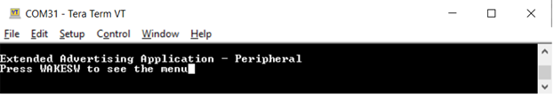
Advertizing external Peripheral start screen
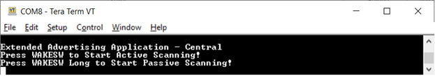
Advertizing external Central start screen
On the board that implements the adv_ext_peripheral application, press the WAKESW button. The board exits Deep-sleep mode and displays the menu as shown in the figure below.
Choosing a menu option on adv_ext_peripheral
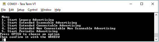
Use the OPTSW to choose an option. The option printed on the bottom changes every time the switch is pressed. When the option matches your intention (For example, 3 Starts Extended Connectable Advertising), press the WAKESW again to make a decision. The advertising type chosen is started and the board starts entering low-power between advertising events.
Next time, the WAKESW is pressed, an updated menu is printed (For example, at option 3 Stop Extended Connectable Advertising). There is no timeout for advertising. The board continues advertising until it is stopped, or a connection is established (for legacy and extended connectable advertising only) with an adv_ext_central device.
The connection is terminated five seconds after the central device configures notifications for the temperature value. When all advertising is off and all connections are terminated, the board enters low-power mode until the WAKESW button is pressed again.
When
gAppLowpowerEnabled_dis set0, LEDs are enabled. The ADVLED flashes whenever an advertising starts and is ON otherwise. The CONNLED flashes whenever there is a connection under way and is ON otherwise.When PAWR is started , advertising data is transmitted on subevents zero and three and responses are expected on all 5 configured response slots of these subevents. The central application responds to the periodic data received with a six bytes data composed of a three bytes random number followed by a three bytes hash performed over the random number using the local IRK in the same fashion the RPA are generated. The advertiser prints the responses, uses the bonded devices IRKs to generate the hash over the random number and attempts to connect over PAWR with the responder in case the hashes match.
PAWR Started
PAWR Set Subevent Data Complete
Periodic advertising response received
Adv Handle: 0
Subevent: 0
Response slot: 2
Response data: EFBE6E573231
Periodic advertising response received
Adv Handle: 0
Subevent: 3
Response slot: 2
Response data: 021CED6395B8
PAWR Set Subevent Data Complete
On the board that implements the adv_ext_central application, there are two options: Press WAKESW to start active scanning or long press WAKESW to start passive scanning. If catching extended scannable advertising is not an option, choose passive scanning. Otherwise, select active scanning. The device wakes up, starts scanning, and enters Deep-sleep mode. The scanning ends when the 60 seconds timeout is reached or when a connection with an adv_ext_peripheral device is established.
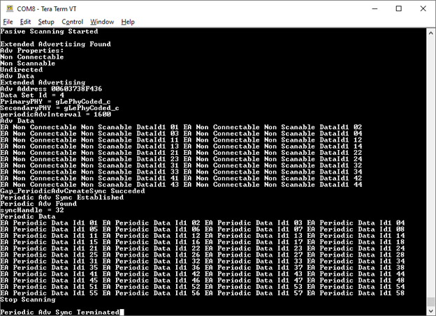
During scanning, all advertisements caught from adv_ext_peripheral devices are displayed on the terminal window as shown in Figure. When an extended non-connectable, non-scannable advertising with a periodic advertising attached is detected, the adv_ext_centraldevice attempts to sync with the periodic advertising train and prints the periodic advertising data on the terminal window.
Advertising caught on adv_ext_central console
If the PAWR support is enabled and the periodic advertising train the adv_ext_central has synced to is with responses the application attempts to sync with the subevents zero and three, periodic advertising data printed being slightly different. Also, the application responds to the periodic data received with a six bytes data composed of a three bytes random number followed by a three bytes hash performed over the random number using the local IRK in the same fashion the RPA are generated. The advertiser uses the bonded devices IRKs to generate the hash over the random number and attempts to connect over PAWR with the responder in case the hashes match.
Passive Scanning Started

Extended Advertising Found
Adv Properties:
Non Connectable
Non Scannable
Undirected
Adv Data
Extended Advertising
Adv Address C4603770BCC5
Data Set Id = 4
PrimaryPHY = gLePhyCoded_c
SecondaryPHY = gLePhyCoded_c
periodicAdvInterval = 2400
Adv Data
EA Non Connectable Non Scanable DataId1 01 EA Non Connectable Non Scanable DataId1 02
EA Non Connectable Non Scanable DataId1 03 EA Non Connectable Non Scanable DataId1 04
Gap_PeriodicAdvCreateSync Succeded
Periodic Adv Sync Established
Gap_SetPeriodicSyncSubevent Succeded
PAWR received
Sync Handle: 0050
Event Counter: 0007
Subevent: 0
Subevent data:
PAWR Data0 For Subevent 0
PAWR Data1 For Subevent 0
Gap_SetPeriodicAdvResponseData Succeded
Periodic Adv Set Response Data Complete
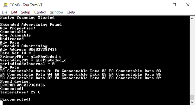
If the adv_ext_central connects to an adv_ext_peripheral device, it bonds (if no bond was previously made), does service discovery (only the first time it connects with the peripheral), configures notification and waits for notifications from the peripheral. If no data is sent within 5 seconds, the node disconnects and reenters Deep-sleep mode. The peripheral sends a notification with the value of the temperature read through an ADC from a thermistor, if present, or randomly generated, if not. When the central receives the notification, it displays it on the terminal window and disconnects in 5 seconds as shown in the figure below.
When the 60 seconds timer expires or the connection ends, the device reenters Deep-sleep mode until the WAKESW is pressed again and all syncs with periodic advertising trains are terminated. If
gAppLowpowerEnabled_dis set0, LEDs are enabled. The SCANLED flashes, whenever the device is scanning and is ON otherwise. The CONNLED flashes, whenever there is a connection under way and is ON otherwise. See the figure below.Connection on adv_ext_central console
When the PAWR support is enabled and a connection with a previously bonded device takes place over PAWR, the applications behavior is similar except in this case the adv_ext_central’s role is peripheral and adv_ext_peripheral’s role is central.
PAWR Started
PAWR Set Subevent Data Complete
Periodic advertising response received
Adv Handle: 0
Subevent: 3
Response slot: 2
Response data: 564DE1FC4957
 Gap_ConnectFromPawr Succeeded
Connected!

Disconnected!
PAWR received
Sync Handle: 0050
Event Counter: 0007
Subevent: 0
Subevent data:
PAWR Data0 For Subevent 0
PAWR Data1 For Subevent 0
Gap_SetPeriodicAdvResponseData Succeded
Periodic Adv Set Response Data Complete

Connected!
Temperature: 24 C

Disconnected!
Parent topic:Low-power extended advertising Peripheral and Central
Parent topic:Bluetooth LE stack and demo applications
Over the Air Programming (OTAP)
This section describes the implemented profiles and services, user interactions, and testing methods for the Bluetooth LE OTAP application.
Implemented profile and services
The Bluetooth LE OTAP applications implement the GATT client and server for the custom Bluetooth LE OTAP profile and service.
Bluetooth LE OTAP Service (UUID: 01ff5550-ba5e-f4ee-5ca1-eb1e5e4b1ce0)
The Bluetooth LE OTAP Service is a custom service which has 2 characteristics.
OTAP Control Point Characteristic (UUID: 01ff5551-ba5e-f4ee-5ca1-eb1e5e4b1ce0). This characteristic can be written and indicated to exchange OTAP Commands between the OTAP Server and the OTAP Client. Data chunks are not transferred using this characteristic.
OTAP Data Characteristic(UUID: 01ff5552-ba5e-f4ee-5ca1-eb1e5e4b1ce0). This characteristic can be written without response by the OTAP Server to transfer image file data chunks to the OTAP Client only when an image block transfer is requested via the ATT transfer method. Data chunks can also be transferred via the L2CAP credit-based PSM channels method.
The demo runs using 3 applications: an OTAP Client embedded application, an OTAP Server embedded application, and an Over the Air Programming PC application. The OTAP Client embedded application has two versions, an ATT version and a L2CAP version each using a different transfer method.
The embedded OTAP Server application is a GAP Central application which scans for devices advertising the Bluetooth LE OTAP service. After it finds one, it connects to it and configures the OTAP Control Point CCC Descriptor to receive ATT Indications from the device then it waits for OTAP commands from this device.
Once commands start arriving from the OTAP Client via ATT Indications the OTAP Server relays them via serial interface to a PC application which responds. The responses are then sent back to the OTAP Client by writing the OTAP Control Point Characteristic. The embedded OTAP Server application effectively acts as a relay between the OTAP Client to which the image is sent over the air and the Over the Air Programming PC application which has an OTAP image file constructed using a binary ‘.srec’ image or a ‘.bin’ image.
The OTAP Client is a GAP Peripheral which advertises the Bluetooth LE OTAP Service and waits for a connection from an OTAP Server. After an OTAP Server connects, the OTAP Client waits for it to write the OTAP Control Point CCCD and then starts sending commands via ATT Indications. If the OTAP Client is configured to ask the data transfer via the L2CAP CoC PSM, it registers and tries to connect a predetermined L2CAP PSM before sending any commands to the OTAP Server.
Parent topic:Over the Air Programming (OTAP)
Supported platforms
The following platforms support the OTAP applications:
KW45B41Z-EVK
K32W148-EVK
FRDM-MCXW71
MCX-W71-EVK
KW47-EVK
FRDM-MCXW72
MCX-W72-EVK
Parent topic:Over the Air Programming (OTAP)
User interface
After flashing two boards with the OTAP Server and OTAP Client applications respectively, the devices are in Idle mode (all LEDs flashing). To start advertising, press the ADVSW button on the OTAP Client. To start scanning, press the SCANSW button on the OTAP Server. After the two devices connect and start exchanging commands. CONNLED becomes solid on the OTAP Server and on the OTAP Client.
Start the OTAP Server PC application after the embedded applications are flashed to the boards. The application creates an OTAP image file using the provided executable .srec or .bin file. It then connects to the embedded OTAP Server via the configured serial interface and waits for commands. The application shows details about the image file creation and allows the OTAP upgrade image file header to be configured. The log view of the application displays the interactions between the OTAP Client and the OTAP Server.
Parent topic:Over the Air Programming (OTAP)
Usage with Over The Air Programming Tool
Below is a list of requirements for usage with Test Tool for Connectivity products:
Over The Air Programming Tool 1.4.0 or newer on CONNECTIVITY-TOOL-SUITE
Serial COM port drivers – these are board-specific.
To run the application, follow the steps below:
Flash the OTAP Server onto a supported platform and the OTAP Client to another supported platform. Make sure the board running the OTAP Server is connected to your PC and your PC has appropriate drivers for the USB to serial device on that board.
Create the application to send over the air. The executable must be provided in the
.srecor.binformat. The.srecformat executable can be obtained by using the IAR Output Converter and setting the output format to Motorola as shown in in the figure below.When compiling an image for the Over-the-Air update, the
gEraseNVMLink_dlinker symbol must be set to0.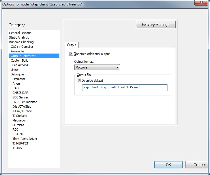
To obtain a
.binfile from IAR, select the Raw binary option in the IAR Output Converter as seen in the in the figure below.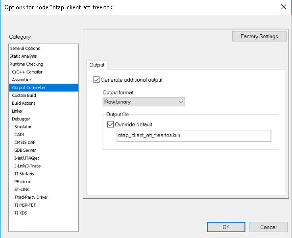
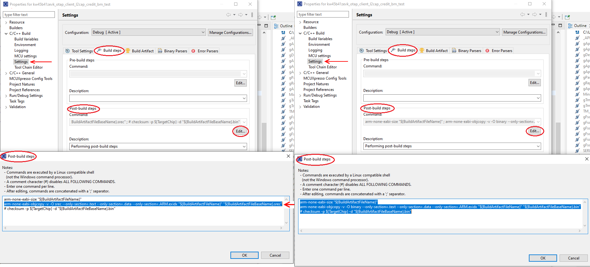
To obtain a
.binfile from MCUXpresso IDE, go to the Project properties -> Settings -> Build stepswindow and press the Editbutton for the Post-build steps. A Post-build steps window shows up. In this window, add the following command:arm-none-eabi-objcopy -v -O binary --only-section=.text --only-section=.data --only-section=.ARM.exidx "${BuildArtifactFileName}" "${BuildArtifactFileBaseName}.bin"
In case the command already exists, uncomment it by removing the ‘#’ character at the beginning.
To obtain a
.srec (.s19)file, add or uncomment the following post-build command in the same window:arm-none-eabi-objcopy -v -O srec --only-section=.text --only-section=.data --only-section=.ARM.exidx" ${BuildArtifactFileName}" "${BuildArtifactFileBaseName}.s19"This window is shown in the figure below.
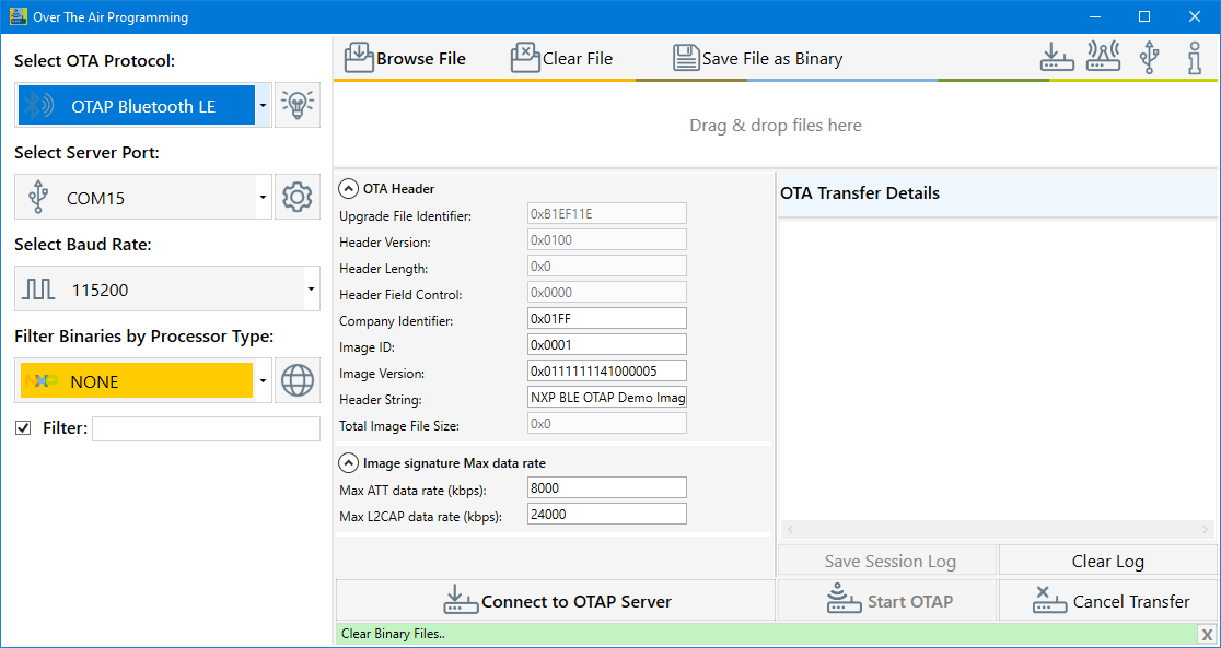
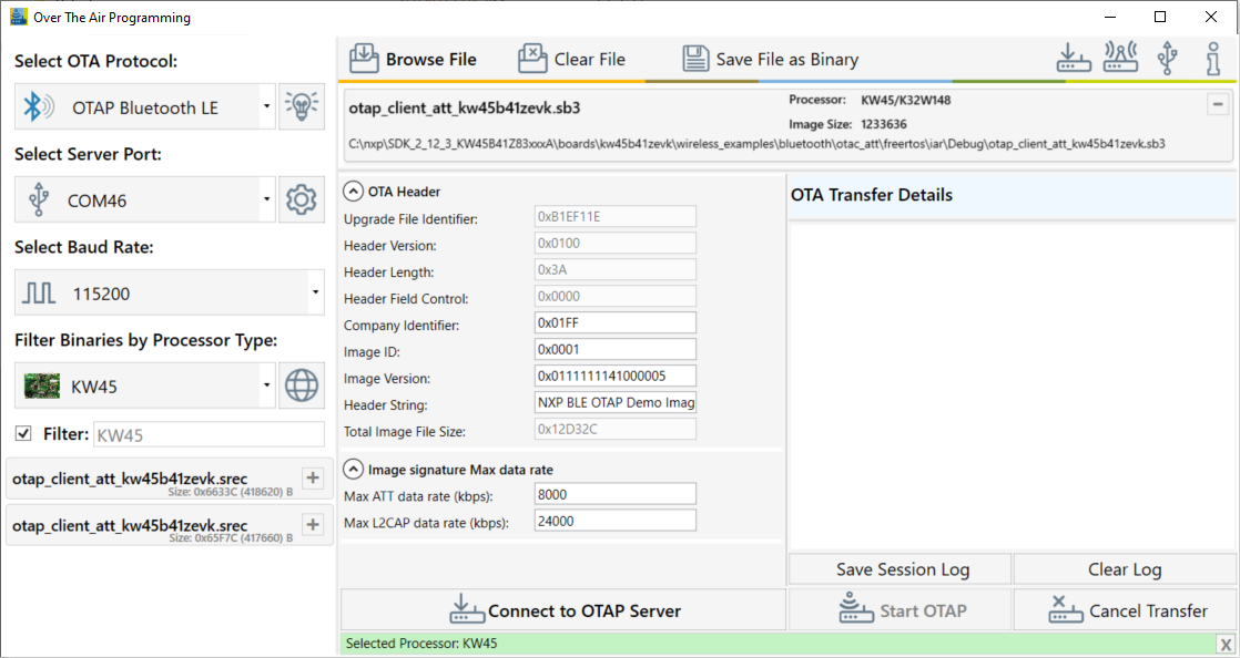
Start the Over The Air Programming application and select “OTAP Bluetooth LE” from the “Select OTA Protocol” combo box as shown in the figure below.
Load the image file into the application, then configure the image file header and start the OTAP Server:
To select the updated image In the Over the Air Programming tool, select the “Browse File” button and then navigate to the
.srecor.binfile containing the image to be sent to the OTAP Client. After the.srecor.binfile is chosen, a pop-up window asks to choose the target processor. In this example, the KW45/K32W processor will be used. Choose the KW45/K32W processor and press OK. See the figure below.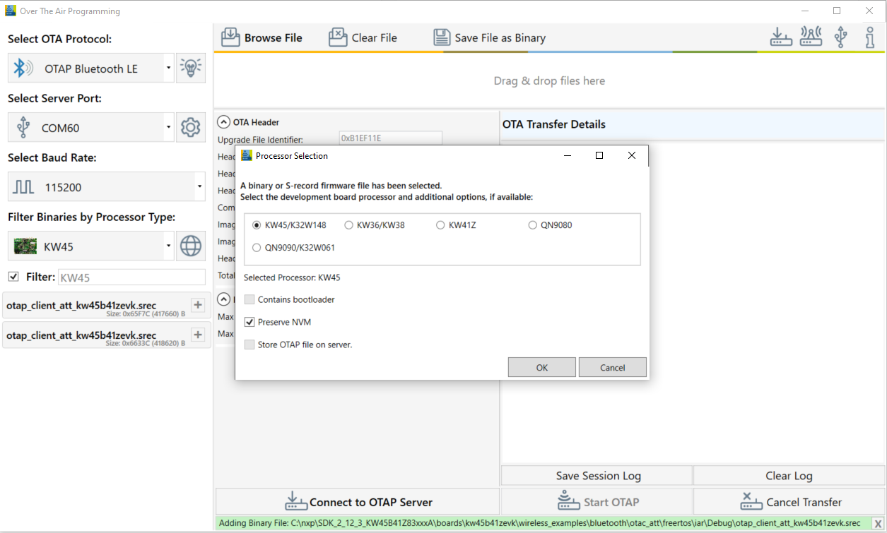
Once the processor is selected, a new pop-up window would appear that allows selecting the type of image as shown in the figure below.
(In the specified case, we selected the KW45Z/KW45Z/K32W1(MCU).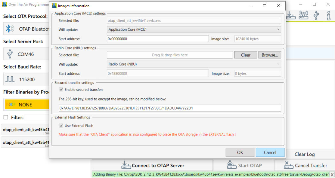
To update the KW45B/KW32W1 (radio) image, select it by pressing the “Browse” button in the M3 group. Then navigate to the
.binfile as shown in the figure below.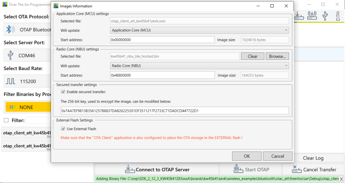
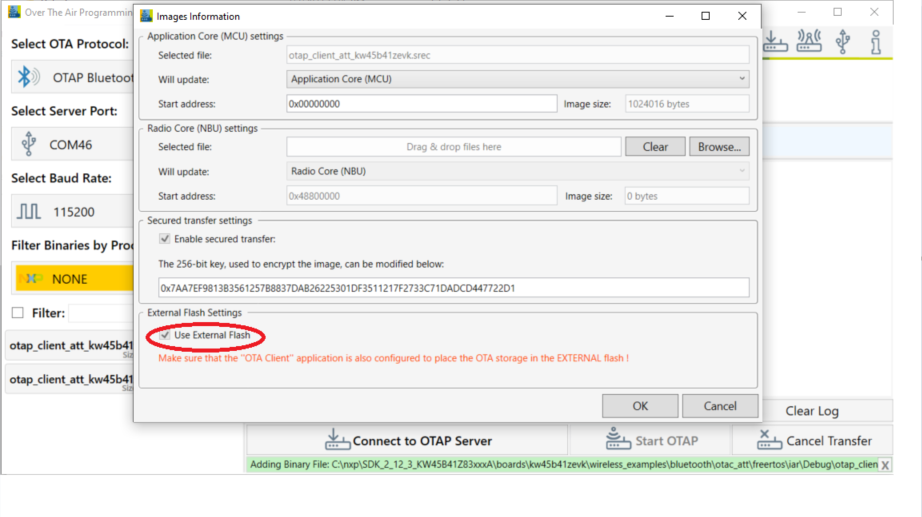
If the OTA client has configured external memory support, then “Use External Flash” checkbox must be checked as in the figure below. If the OTA client has configured internal memory support, the checkbox must be left unchecked.
This checkbox (if checked) instructs the OTA client bootloader to erase all the internal storage. This must be done only if external memory support is used as shown in the figure below.
.
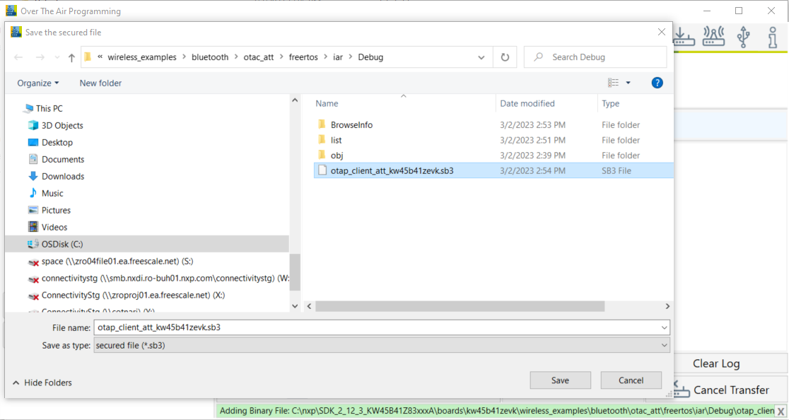
At this moment, click the OKbutton. A new window appears that prompts you to enter a location where the secured file should be stored. By default, the location of the original file is selected. See the figure below.
Note: The extension of the secured file is *.sb3. See the figure below.
You can now configure two different JSON files, used to:
Sign the file that is uploaded to the MCU if an MCU file was selected.
Create the *.sb3container that is sent OTA. The *.sb3 file can contain only the MCU file, only the radio file, or both.
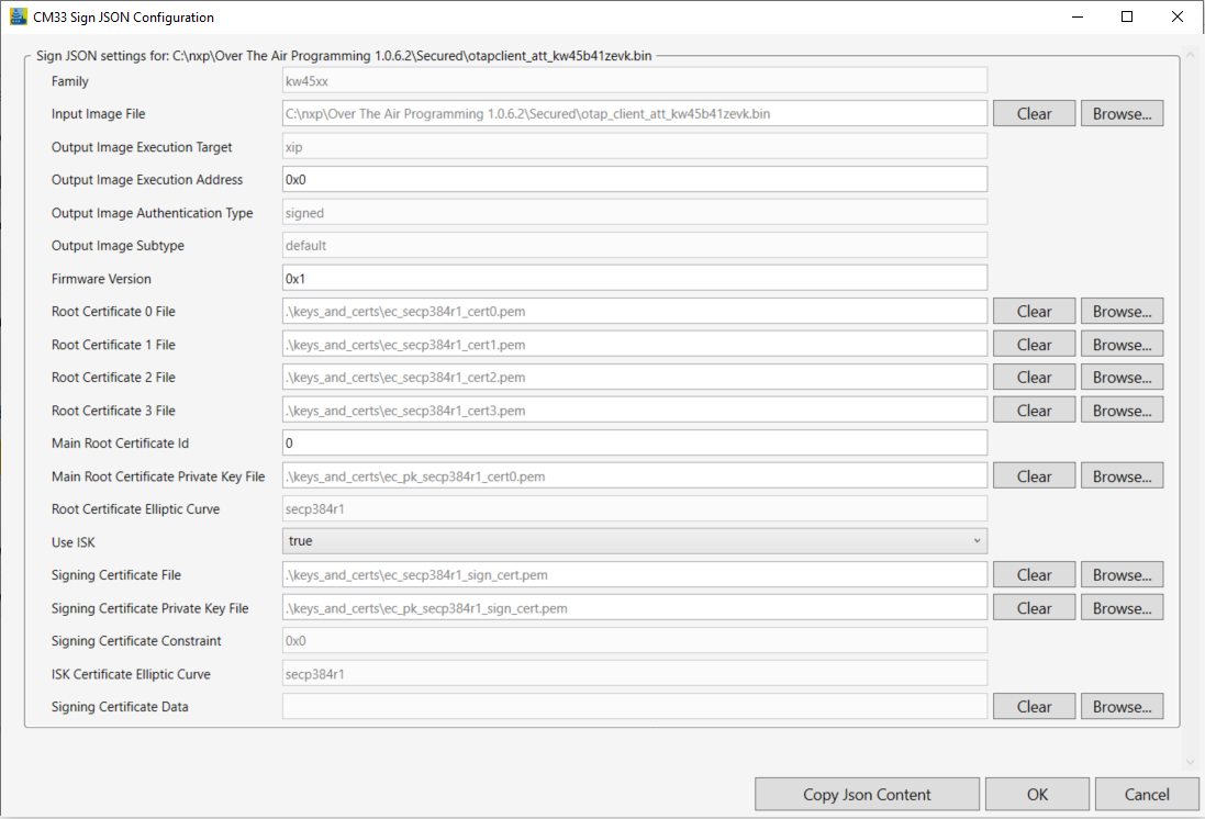
If you select a file that is written on the MCU, a new window appears as shown in the figure below. This window helps in configuring the root certificates and signing the certificates, by either dragging and dropping, or browsing for new files. For details on each field of the JSON, see /Documentation/KW45JsonDescription.pdf provided with Over the Air Programming tool.
By default, the JSON is configured for the demo applications to run as shown in the figure below.
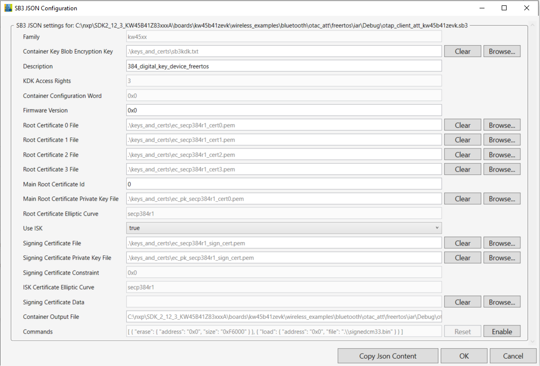
After configuring the JSON file used for signing the MCU file, a new similar window appears. As shown in the Figure, the window is designed for configuring the *.sb3 container. This window helps you to configure the encryption key file, the root certificates, and the signing certificates by either drag and dropping or browsing for new files. For details on each field of the JSON file, see /Documentation/KW45JsonDescription.pdf provided with Over the Air Programming tool.
By default, the JSON is configured for the demo applications to run as shown in the figure below.
After the
.sb3file is created, the “Encryption Key” and “Authentication Key” are presented. For the secured update to be successful, the destination board must have been provisioned with these keys through fuse burning, as described in the accompanying document. Depending on the board type, it can either be already provisioned by NXP (KW45\KW47\MCX-W71\MCX-W72 samples) or not provisioned (loose samples). See the figure below.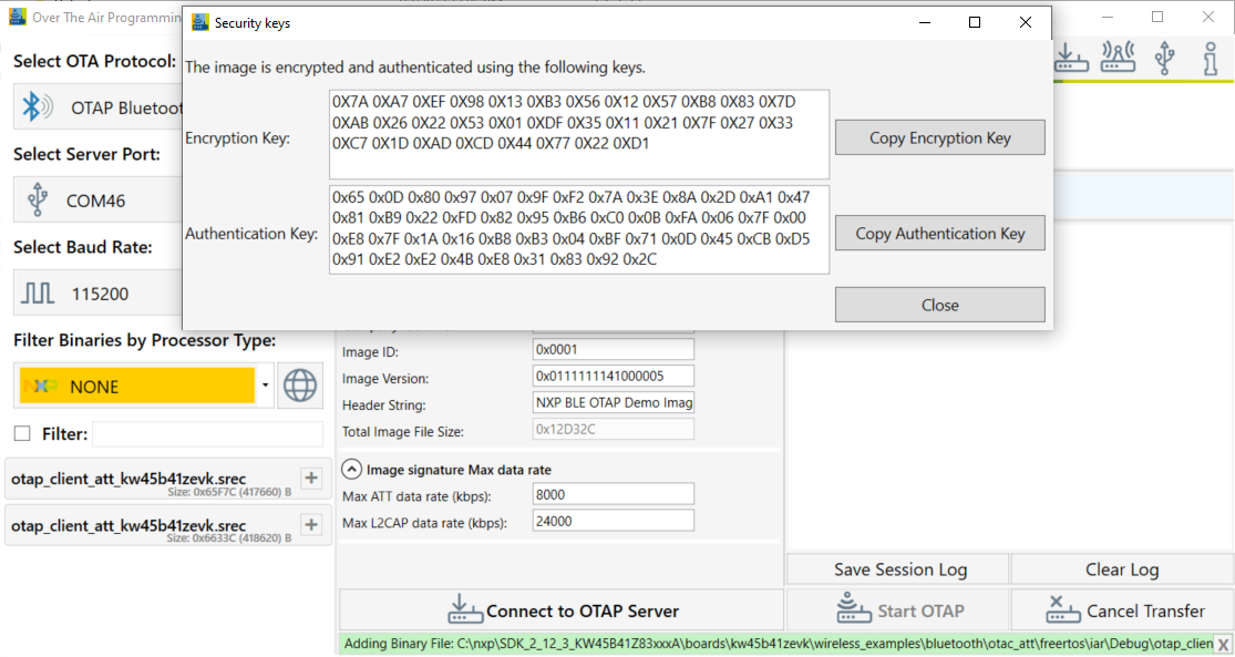
The OTA Header configuration options from the “OTA Header” box are used by the application to build the OTAP Image File, which is sent over the air. The default values of the OTA Header configuration work out of the box for the OTAP demo applications. For details about these configuration options, see the Bluetooth LE Application Developer’s Guide document (BLEADG).
After the image is loaded, go to the “Select Server Port” box, select the correct COM Port for the OTAP Server board. Also select the default baud rate of 115200 and press the “Connect to OTAP Server” button. A successful connection is displayed in the Message Log.
If the image is loaded before connecting to the OATP Server COM Port, then the OTAP Server of the application starts automatically.
If the connection to the COM Port is established before the image is loaded, then the “Start OTAP” button must be pressed to start the OTAP Server of the application. For details, see the figure below.
.
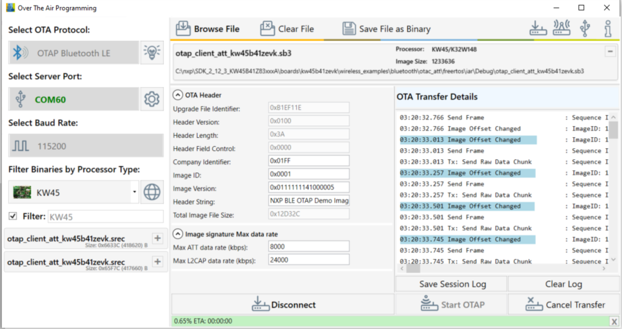
Before starting the image transfer process, the data rate must be configured for each transfer method (ATT or L2CAP CoC). The image chunks of a block are sent over the serial interface and over-the-air without waiting for confirmation. Data rate can significantly slow down if configuration is not done correctly and errors appear in the transfer process.
The optimal data rate depends on multiple factors. Some of these factors are listed below:
Distance between boards
Type of antenna
Performance of the RF circuitry between the radio and antenna
Type and level of noise in the environment
Speed of the storage medium in which the image is saved on the OTAP Client
Serial driver delay between PC and the OTAP Server board If the data rate is too high, then the OTAP Client receives a new chunk before it can process the previous one. In such a case, it sends an “Unexpected Chunk Sequence Number” error and restarts the transfer of the current block from where it left off. If the channel is too noisy, the transmitter can be flooded and some chunks might not reach the client triggering a similar type of error. The default data rate values should work for most configurations.
Start the embedded applications by pressing ADVSW first on the OTAP Client and then on the OTAP Server. The transfer progress and transfer-related messages and/or errors are shown in the application window. The duration of the transfer depends on the size of the image and the chosen data rate and transfer method. See the figure below.
After all the blocks are sent, the OTAP Client sends an
Image Transfer Completecommand to the OTAP Server. When the PC Application receives this command, it displays aSent Image with Successmessage in the log window. See the figure below.
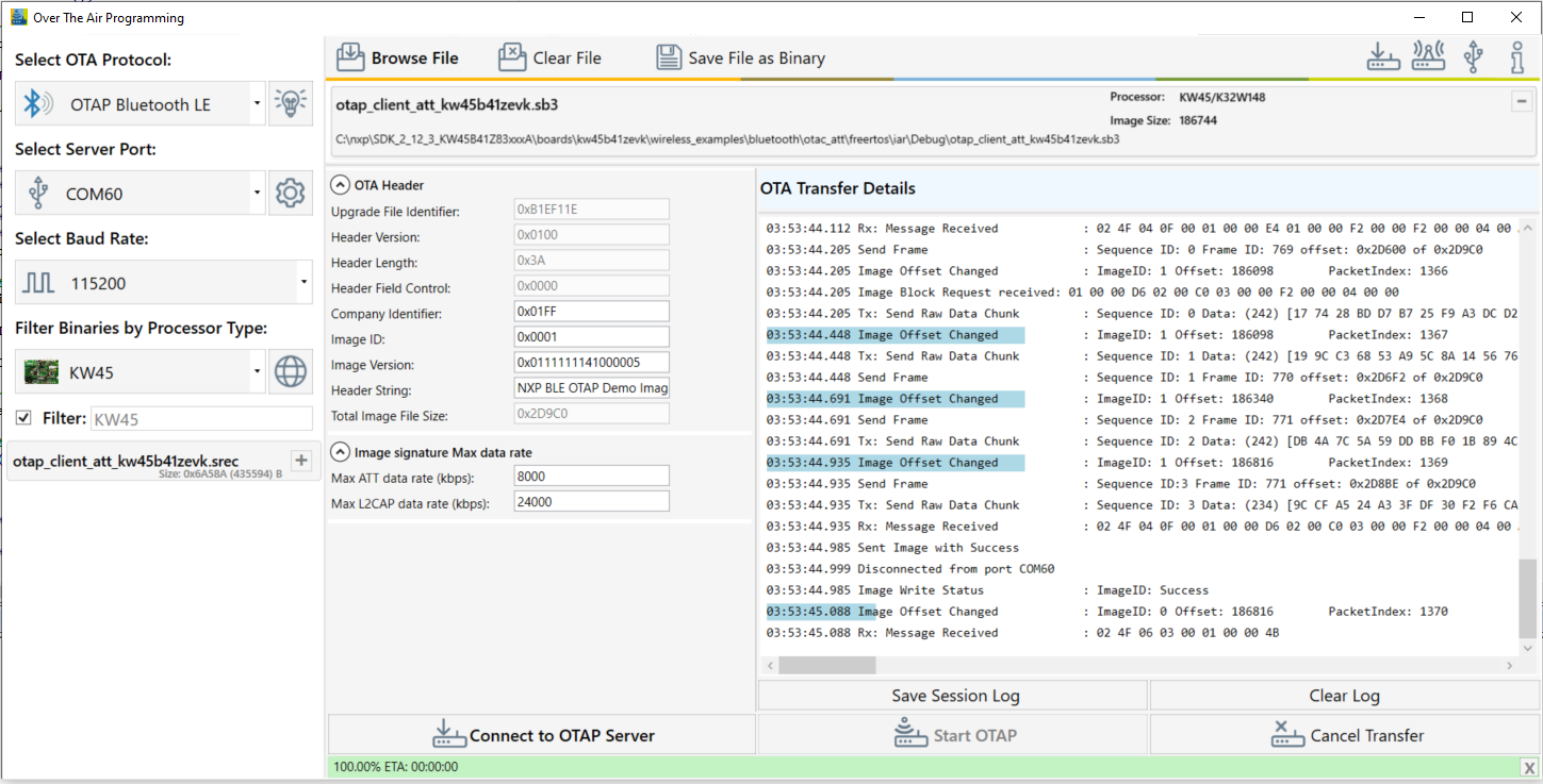
After the image transfer is complete, the OTAP Client triggers the bootloader and resets the MCU. The bootloader takes about 30 seconds to flash the image on the board. After this time frame, the MCU resets again and runs the new image.
Parent topic:Over the Air Programming (OTAP)
Storage type selection
OTAP Clients support both internal and external storage. By default, the applications come with internal storage enabled. To configure external storage, follow the steps bellow:
Set the
gUseInternalStorageLink_ddefine to0in the project settings.In
app_preinclude.h, set thegAppOtaExternalStorage_cdefine to1.
Usage with IoT Toolbox
This is the list of requirements.
Mobile device running Android platform or iOS with hardware and software supporting Bluetooth 4.0 and later.
Kinetis Bluetooth LE Toolbox application – download from the specific application store for your device.
To run the application, perform the following steps:
Flash the OTAP Client ATT to either the KW45B41Z-EVK or the K32W148-EVK platform. The Kinetis Bluetooth LE Toolbox only supports the ATT OTAP Client.
In order to send over the air in
.bleotaformat, create the application. In order to load the image file into the Over the Air Programming application and create the .sb3 file, follow the instructions described in Usage with Over The Air Programming Tool. Once the.sb3file is created, press the “Save File as Binary” button to create the.bleotafile. See the figure below.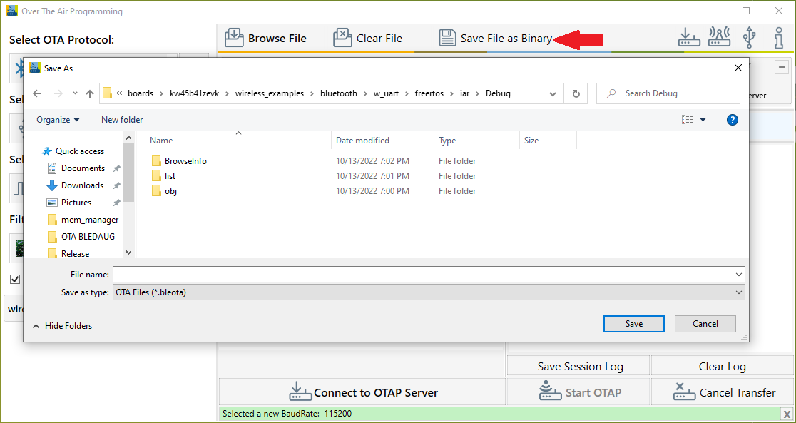
Start the Kinetis Bluetooth LE Toolboxapplication on your mobile device and start the OTAP Tool. The application starts scanning.
Press ADVSW on the board to start Advertising on the embedded OTAP Client application. The device should show up in the list of scanned devices. Touch the device in the scan list to connect to and the application performs service discovery and displays some information shown in the figure below.
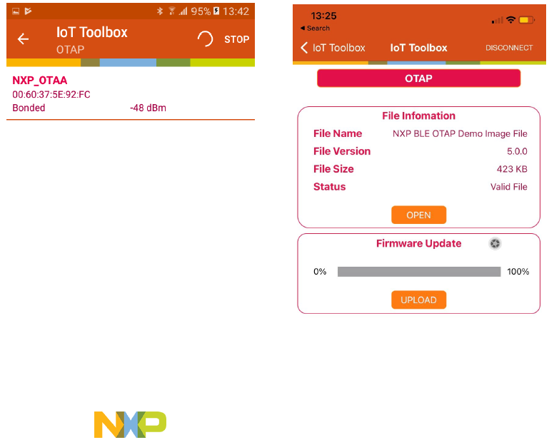
Press the “Open” button and load the
.bleotafile to be sent over-the-air. Once the file is loaded, some information about it is displayed. Press the “Upload” button to start the image transfer process. A progress bar is shown while the image transfer is ongoing. The progress bar displays 100% update after a successful transfer, as shown in the figure below.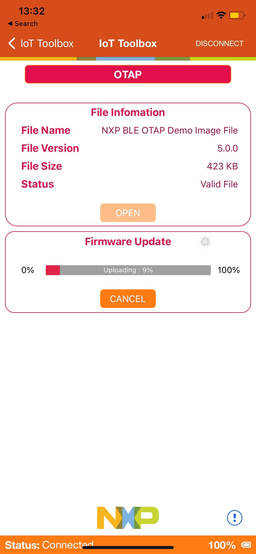
After the image transfer is complete, the OTAP Client triggers the bootloader and resets the MCU. The bootloader takes about 30 seconds to flash the image on the board. After this time passes, the MCU resets again and runs the new image.
Parent topic:Over the Air Programming (OTAP)
Parent topic:Bluetooth LE stack and demo applications
Wireless UART
This section describes the implemented profiles and services, user interactions, and testing methods for the Wireless UART application.
Implemented profile and services
The Wireless UART application implements both the GATT client and server for the custom Wireless UART profile and services.
Wireless UART Service (UUID: 01ff0100-ba5e-f4ee-5ca1-eb1e5e4b1ce0)
Battery Service v1.0
Device Information Service v1.1
The Wireless UART service is a custom service that implements a custom writable ASCII Char characteristic (UUID: 01ff0101-ba5e-f4ee-5ca1-eb1e5e4b1ce0) that holds the character written by the peer device.
The application behaves at first as a GAP central node. It enters GAP Limited Discovery Procedure and searches for other Wireless UART devices to connect. To change the device role to GAP peripheral, use the ROLESW button. The device enters GAP General Discoverable Mode and waits for a GAP central node to connect.
Parent topic:Wireless UART
Supported platforms
The following platforms support the Wireless UART application:
KW45B41Z-EVK
KW45B41Z-LOC
K32W148-EVK
FRDM-MCXW71
MCX-W71-EVK
KW47-EVK
KW47-LOC
FRDM-MCXW72
MCX-W72-EVK
Parent topic:Wireless UART
User interface
After flashing the board, the device is in idle mode (all LEDs flashing). To start scanning, press the SCANSW button. When in GAP Limited Discovery Procedure of GAP General Discoverable Mode, CONNLED is flashing. When the node connects to a peer device, CONNLED turns solid. To disconnect the node, hold the SCANSW button pressed for 2-3 seconds. The node then re-enters GAP Limited Discovery Procedure.
Parent topic:Wireless UART
Usage
The application is built to work with another supported platform running the same example or with the Wireless UART from the IoT Toolbox application.
When testing with two boards, perform the following steps:
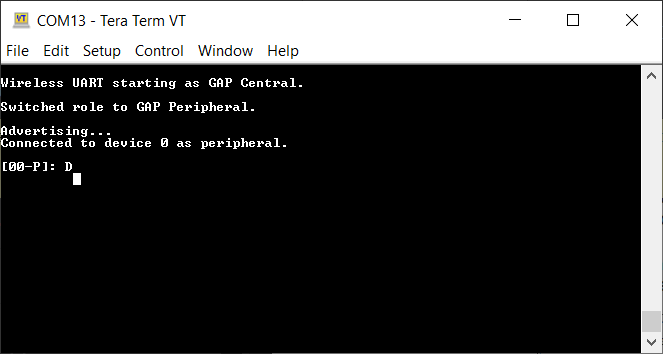
Open a serial port terminal and connect them to the two boards, in the same manner described in Testing devices. The start screen is blank after the board is reset.
The application starts as a GAP central. To switch the role to a GAP peripheral, press the role switch. Depending on the role, when pressing the SCANSW, the application starts either scanning or advertising.
As soon as the CONNLED turns solid on both devices, the user can start writing in one of the consoles. The text appears on the other terminal.
After creating a connection, the role (central or peripheral) is displayed on the console. The role switch can be pressed again before creating a new connection. See the figure below.
Tera Term – received text on Wireless UART

When testing with a single board and the IoT Toolbox, perform the following steps:
Open a serial port terminal and connect the board in the same manner described in Testing devices. The start screen is blank after the board is reset.
Press the role switch button to behave as a GAP peripheral and then press the SCANSW button to start advertising. The IoT Toolbox app can then connect. Select UART instead of Console and start typing, as shown in the Figure.
Parent topic:Wireless UART
Parent topic:Bluetooth LE stack and demo applications
Bluetooth LE Shell
This section describes the functionality, user interactions, and testing methods for the Bluetooth LE Shell Application.
Implemented stack features
The Bluetooth LE Shell Application implements a console application that allows the user to interact with a full feature Bluetooth Low Energy stack library. It implements All GAP roles and both GATT client and server. Enabling these roles can be done using shell commands.
Parent topic:Bluetooth LE Shell
Implemented profile and services
The application implements a dynamic GATT database. The user can add services at runtime and also erase the database contents. The database is always populated with the GAP and GATT services. These services cannot be erased. The user can dynamically add the following services:
Heart Rate Service (UUID: 0x180D)
Battery Service (UUID: 0x180F)
Device Information Service (UUID: 0x180A)
Internet Support Profile Service (0x1820)
Parent topic:Bluetooth LE Shell
Supported platforms
The following platforms support the Bluetooth LE Shell application:
KW45B41Z-EVK
K32W148-EVK
FRDM-MCXW71
MCX-W71-EVK
KW47-EVK
FRDM-MCXW72
MCX-W72-EVK
Parent topic:Bluetooth LE Shell
User interface
After flashing the board, the device is in idle mode. The interaction with the board is done entirely by using the shell commands via the serial communication terminal.
Parent topic:Bluetooth LE Shell
Usage
The application is built to work with any other Bluetooth LE device. To showcase the functionality, two platforms are used in the following setup.
Open a serial port terminal and connect them to the two boards, in the same manner described in Testing devices. The start screen is displayed after the board is reset. All LEDs are flashing on both devices.
Configure one of the devices as a GAP peripheral and a Heart Rate server. Change name to HRS. Start advertising on this device.
BLE Shell>gap devicename HRS
--> GATTDB Event: Attribute Written
HRS>gap advdata 1 6
HRS>gap advdata 8 HRS
HRS>gap advstart
HRS>
--> GAP Event: Advertising parameters successfully set.
HRS>
--> GAP Event: Advertising data successfully set.
HRS>
--> GAP Event: Advertising state changed successfully!
HRS>gattdb addservice 0x180D
--> Heart Rate
- Heart Rate Measurement Value Handle: 14
Configure the other device as a GAP central. Change its name to ‘Collector’. Start scanning and connect to the HRS device by selecting the corresponding device index from the list of scanned devices. In the example below, the HRS device is device number 2. The number of listed scanned devices can be controller through the
mShellGapMaxScannedDevicesCount_cdefine inshell_gap.c.BLE Shell>gap devicename Collector --> GATTDB Event: Attribute Written Collector>gap scanstart filter --> GAP Event: Scan started. Collector> --> GAP Event: Found device 0 : 880F102F500E 0 dBm --> GAP Event: Found device 1 : NXP_CSCS 00049F000006 0 dBm --> GAP Event: Found device 2 : HRS 00049F0000FF 0 dBm Collector>gap connect 2 --> GAP Event: Scan stopped. Collector> --> GAP Event: Connected to peer 0
Optionally, the devices can be paired (gAppUsePairing_d and gAppUseBonding_d must be set in app_preinclude.h). On the collector initiate the pairing.
Collector>gap pair 0
--> Pairing...
--> GAP Event: Link Encrypted
--> GAP Event: Device Paired
On the Collector, start service discovery. The device discovers the GAP, GATT, and Heart Rate services.
Collector>gatt discover 0 -all
--> Discovered primary services: 3
--> Generic Attribute Start Handle: 1 End Handle: 4
- Service Changed Value Handle: 3
- Client Characteristic Configuration Descriptor Handle: 4
--> Generic Access Start Handle: 5 End Handle: 11
- Device Name Value Handle: 7
- Appearance Value Handle: 9
- Peripheral Preferred Connection Parameters Value Handle: 11
--> Heart Rate Start Handle: 12 End Handle: 19
- Heart Rate Measurement Value Handle: 14
- Client Characteristic Configuration Descriptor Handle: 15
- Body Sensor Location Value Handle: 17
- Heart Rate Control Point Value Handle: 19
Configure the HRS to send notifications by writing the CCCD from the Collector. Send a GATT write command with value
1to the CCCD handle discovered, 15.Collector>gatt write 0 15 0x0001 --> GATT Event: Characteristic Value Written!
Send heart rate measurement notifications from the HRS device by using the value handle obtained after adding the service in the previous step.
HRS>gatt notify 0 14
A notification appears on the Collector console.
Collector>
--> GATT Event: Received Notification
Handle: 14
Value: B400
Extended advertising
Use the Bluetooth LE Shell application to exercise the advertising extension features:
On the GAP Peripheral device:
Configure the extended advertising parameters. In the below example, the advertising type is set to connectable and includes TX power and the primary PHY is set to Coded PHY.
Configure the extended advertising data. The Bluetooth LE Shell applications has the feature to send for test, a large data payload. Use the extended advertisement default configuration (not call “
gap extadvcfg”), pass the command “gap extadvdata” with no parameters and the default data is added. The length is configurable at compile time throughSHELL_EXT_ADV_DATA_SIZEand the data pattern isSHELL_EXT_ADV_DATA_PATTERN. Start the default test with call for “gap extadvstart”.The advertising data type is set to shortened local name (8) and the advertising data content is set to
test_ext_adv_data.Note: Users must note that extended connectable advertising does not allow for chained advertising data. The data length must be limited to what can fit in a single AUX_ADV_IND PDU (251 bytes at maximum). This means that passing the
gap extadvdatawith no parameters and the default value ofSHELL_EXT_ADV_DATA_SIZE(500 bytes) after having set the advertising type to connectable will result in an error when trying to start advertising.Start extended advertising.
BLE Shell>gap extadvcfg -type 65 -phy1 3
BLE Shell>gap extadvdata 8 test_ext_adv_data
BLE Shell>gap extadvstart
--> GAP Event: Extended
Advertising parameters successfully set.
--> GAP Event:
Extended Advertising data successfully set.
--> GAP Event: Advertising state changed successfully!
On the GAP Central device
Set the scanning parameters. The scanning PHY is set to match the advertising PHY, in this case Coded PHY.
Start scanning and filter duplicates.
BLE Shell>gap scancfg -phy 4
BLE Shell>gap scanstart filter
BLE Shell>
-> GAP Event: Scan started.
BLE Shell>
--> GAP Event: Found device 0 : 0060375BCEC6 -23 dBm
Advertising Extended Data:
test_ext_adv_data
Set the connection initiating PHYs corresponding to the primary PHY on which the advertising is performed.
Connect to the desired device in the scanned devices list.
BLE Shell>gap connectcfg -phy 4
--> Connection Parameters:
--> Connection Interval: 200 ms
--> Connection Latency: 0
--> Supervision Timeout: 32000 ms
--> Connecting PHYs: Coded
BLE Shell>gap connect 0
BLE Shell>
-> GAP Event: Scan stopped.
BLE Shell>
--> GAP Event: Connected to peer 0
Parent topic:Usage
RSSI Monitor
RSSI Monitor is an application that allows monitoring the RSSI of a remote peer on advertising or connection channel. The GAP peripheral device can modify the output TX power on both advertising and connection channels.
On GAP peripheral device
Set the primary advertising PHY to Coded PHY. Start advertising and read the address. Set the TX power in dBm to a value less than 20 dBm.
BLE Shell>gap address
BLE Shell>
--> GAP Event: Public Address Read:C4603770BCC5
BLE Shell>gap extadvcfg -phy1 3
BLE Shell>gap extadvstart
BLE Shell>
--> GAP Event: Extended Advertising parameters successfully set.
BLE Shell>
--> GAP Event: Extended Advertising data successfully set.
BLE Shell>
--> GAP Event: Advertising state changed successfully!
BLE Shell>gap txpower adv 0
BLE Shell>
--> GAP Event: Success!
On GAP Central device
Set the scanning PHY to Coded PHY. Start monitoring the RSSI on advertising Channel using the address of the Peripheral device. Scanning starts automatically, if it is not previously enabled.
BLE Shell>gap scancfg -phy 4
BLE Shell>gap rssimonitor C4603770BCC5--> Reading RSSI on advertising channel:
BLE Shell>
-> GAP Event: Scan started.
BLE Shell>
 RSSI: -27 dBm
 RSSI: -27 dBm
 RSSI: -27 dBm
 RSSI: -27 dBm
 RSSI: -27 dBm
 RSSI: -29 dBm
In the below example, the RSSI in monitored on a connection channel. On GAP Peripheral, start advertising in connectable mode on Coded PHY and adjust the TX power level.
BLE Shell>gap extadvcfg -type 65 -phy1 3
BLE Shell>gap extadvdata 8 rssimonitortest
BLE Shell>gap extadvstart
BLE Shell>
--> GAP Event: Extended Advertising parameters successfully set.
BLE Shell>
--> GAP Event: Extended Advertising data successfully set.
BLE Shell>
--> GAP Event: Advertising state changed successfully!
BLE Shell>
--> GAP Event: Connected to peer 0
BLE Shell>
--> GAP Event: Advertising stopped!
BLE Shell>gap txpower conn 10
BLE Shell>
--> GAP Event: Success!
On the GAP Central device, start scanning on the Coded PHY. Update the connection PHY also to Coded PHY, then connect to the remote device and monitor continuously the RSSI on the connection channel.
BLE Shell>gap scancfg -phy 4
BLE Shell>gap connectcfg -phy 4
-->  Connection Parameters:
    -->  Connection Interval: 200 ms
    -->  Connection Latency: 0
    -->  Supervision Timeout: 32000 ms
    -->  Connecting PHYs: Coded
BLE Shell>gap scanstart filter
BLE Shell>
->  GAP Event: Scan started.
BLE Shell>
-->  GAP Event: Found device 0 : C4603770BCC5 -21 dBm
 Advertising Extended Data:
rssimonitortest
gap connect 0
BLE Shell>
->  GAP Event: Scan stopped.
BLE Shell>
-->  GAP Event: Connected to peer 0
BLE Shell>gap rssimonitor 0 -c
-->  Reading RSSI from connected device:
BLE Shell>
 RSSI: -22 dBm
 RSSI: -23 dBm
 RSSI: -21 dBm
 RSSI: -22 dBm
 RSSI: -22 dBm
BLE Shell>gap rssistop
Update the PHY preference and continue monitoring the RSSI. For coded PHY, the coding scheme can be configured between S2 and S8 (500 kbit/s and 125 kbit/s).
BLE Shell>gap phy 0 -tx 4 -rx 4 -o 1
BLE Shell>
--> GAP Event: Phy update complete with peer 0
--> TxPhy: Coded
--> RxPhy: Coded

BLE Shell>gap phy 0 -tx 2 -rx 2
BLE Shell>
--> GAP Event: Phy update complete with peer 0
--> TxPhy: 2M
--> RxPhy: 2M

BLE Shell>gap rssimonitor 0 -c
--> Reading RSSI from connected device:
BLE Shell>
RSSI: -23 dBm
RSSI: -23 dBm
RSSI: -21 dBm
RSSI: -21 dBm
--> GAP Event: Phy update complete with peer 0
--> TxPhy: Coded
--> RxPhy: Coded

BLE Shell>
RSSI: -22 dBm
RSSI: -21 dBm
RSSI: -22 dBm
RSSI: -23 dBm
RSSI: -23 dBm
--> GAP Event: Phy update complete with peer 0
--> TxPhy: 2M
--> RxPhy: 2M
BLE Shell>
RSSI: -22 dBm
RSSI: -21 dBm
RSSI: -21 dBm
RSSI: -20 dBm
Parent topic:Usage
Parent topic:Bluetooth LE Shell
Throughput feature
The Bluetooth LE Shell application also has a throughput test feature that can be used to test different combinations of the parameters (connection interval, payload size, and packet count) to determine the best data-rate.
This feature requires two devices:
GAP Peripheral: transmits the test packets
GAP Central: receives the packets and displays a report
All throughput-related commands are grouped under the **thrput** keyword:
thrput setparam: configures connection interval, packet count and payload size.thrput start tx: configures the device as a GAP Peripheral and starts advertising. Once the receiving device is connected, the packet transmission begins. The packet size and count can also be specified (-s<size_value>-c<count_value>).thrput start rx: configures the device as a GAP Central and starts scanning. Once a transmitter device is found, it connects to it and waits for the test to begin. The connection interval can also be configured (-ci<value>).thrput stop: stops the test and disconnects the devices.
Once a connection is established between the devices and initial throughput test is complete, one can start a new throughput transmission test with a new set of parameters (packet size / count).
The receiving device generates the report if no packets are received for more than three consecutive connection events.
The default configuration of the throughput test is the following:
Packet count: 1000
Payload size: 20 bytes
Connection interval (min, max): 160, 160 (200 ms)
The example of a test report is shown below:
BLE Shell>thrput start tx
BLE Shell>
-->  GAP Event: Advertising parameters successfully set.
BLE Shell>
-->  GAP Event: Advertising data successfully set.
BLE Shell>
-->  GAP Event: Advertising started.
-->  GAP Event: Connected to peer 0
BLE Shell>
-->  GAP Event: Advertising Throughput test started.
Sending packets...
-->  MTU Exchanged.
BLE Shell>
Throughput test with peer 0 has finished.

BLE Shell>thrput start rx
BLE Shell>
->  GAP Event: Scan started.
Found device:
THR_PER
0060375BCEC6
->  GAP Event: Scan stopped.
-->  GAP Event: Connected to peer 0
BLE Shell>Throughput test started.
Receiving packets...


************************************
***** TEST REPORT FOR PEER ID 0 ****
************************************
Packets received: 1000
Total bytes: 244000
Receive duration: 5017 ms
Average bitrate: 389 kbps
************************************
********** END OF REPORT ***********
Parent topic:Bluetooth LE Shell
Decision-Based Advertising Filtering (DBAF) feature
The Bluetooth LE Shell application also supports the Decision-Based Advertising Filtering (DBAF) feature, which can be enabled by performing the following steps:
Flash the NBU: for KW45B41Z-EVK/K32W148-EVK/FRDM-MCXW71 flash the experimental NBU found in
middleware/wireless/ble_controller/bin/experimental; for KW47-EVK/MCX-W72-EVK/FRDM-MCXW72 flash the all-purpose NBU found inmiddleware/wireless/ble_controller/bin.Update the application project so that it uses the experimental Bluetooth LE Host library:
middleware/wireless/bluetooth/host/lib_exp/lib_ble_OPT_host_cm33_iar.aIn
app_preinclude.hfile, setBLE_SHELL_DBAF_SUPPORTto1.
This feature requires two devices:
GAP Peripheral: transmits decision PDUs (ADV_DECISION_IND).
GAP Central: scans for decision PDUs and handles filtering policies.
To showcase the functionality, two platforms are used in the following setup.
Steps to perform on the GAP Peripheral device:
Configure the extended advertising parameters to use decision PDUs. In the below example, the advertising type is set to connectable and includes TX power, uses decision PDUs and includes AdvA in the decision PDU. The primary PHY is set to Coded PHY.
Configure the extended advertising data using the
gap extadvdecdatacommand. The resolvable tag and/or arbitrary data can be set using the parameters available.Start extended advertising.
BLE Shell>gap extadvcfg -phy1 3 -type 449
BLE Shell>gap extadvdecdata -key 112233445566778899AABBCCDDEEFF00 -prand 5AC317 -decdata 6362 -datalen 2 -restag 0
BLE Shell>gap extadvstart
BLE Shell>
--> GAP Event: Extended Advertising parameters successfully set.
BLE Shell>
--> GAP Event: Extended Advertising data successfully set.
BLE Shell>
--> GAP Event: Extended Advertising Decision Data Setup Complete.
BLE Shell>
--> GAP Event: Advertising state changed successfully!
BLE Shell>
Steps to perform on the GAP Central device:
Set the scanning parameters to scan only decision PDUs. The scanning PHY is set to match the advertising PHY, in this case Coded PHY.
Set the connection parameters to use only decision PDUs and the connection initiating PHYs corresponding to the primary PHY on which the advertising is performed.
BLE Shell>gap scancfg -phy 4 -filter 12
BLE Shell>gap connectcfg -phy 4 -filter 2
--> Connection Parameters:
 --> Connection Interval: 200 ms
 --> Connection Latency: 0
 --> Supervision Timeout: 32000 ms
 --> Connecting PHYs: Coded
 --> Connection Filter Policy: 2
BLE Shell>
Add decision instructions using the
gap adddecinstrcommand. A maximum ofgMaxNumDecisionInstructions_cinstructions can be added. If the set of instructions must be changed, thegap deldecinstrcommand deletes all current instructions.BLE Shell>gap adddecinstr -group 1 -field 0 -criteria 1 -restagkey 112233445566778899AABBCCDDEEFF00 BLE Shell>gap adddecinstr -group 1 -field 6 -criteria 1 -advmode 6 BLE Shell>gap adddecinstr -group 0 -field 24 -criteria 1 -arbmask 00000000ffffff BLE Shell>gap adddecinstr -group 0 -field 9 -criteria 1 -advacheck 2 -add1type 0 -add1 a6fb0d376000 -add2type 0 -add2 a5fb0d376000 BLE Shell>gap adddecinstr -group 0 -field 7 -criteria 1 -rssimin -80 -rssimax 0 BLE Shell>gap adddecinstr -group 0 -field 8 -criteria 5 -lossmin 0 -lossmax 50 BLE Shell>
Set the decision instructions using the
gap setdecinstrcommand. The instructions are used when listening for advertisements containing decision PDUs.Start scanning and filter duplicates.
Connect to the desired device in the scanned devices list.
BLE Shell>gap setdecinstr
BLE Shell>
--> GAP Event: Decision Instructions Setup Complete.
BLE Shell>gap scanstart filter
BLE Shell>
-> GAP Event: Scan started.
BLE Shell>
--> GAP Event: Found device 0 : C4603770BCC5 -23 dBm
 Advertising Extended Data:
gap connect 0
BLE Shell>
-> GAP Event: Scan stopped.
BLE Shell>
--> GAP Event: Connected to peer 0
BLE Shell>
Parent topic:Bluetooth LE Shell
Periodic Advertising with Responses (PAwR) feature
The Bluetooth LE Shell application also supports the Periodic Advertising with Responses feature, which can be enabled by performing the following steps:
Flash the NBU: for KW45B41Z-EVK/K32W148-EVK/FRDM-MCXW71 flash the experimental NBU found in
middleware/wireless/ble_controller/bin/experimental; for KW47-EVK/MCX-W72-EVK/FRDM-MCXW72 flash the all-purpose NBU found inmiddleware/wireless/ble_controller/bin.Update the application project so that it uses the experimental Bluetooth LE Host library,
middleware/wireless/bluetooth/host/lib_exp/lib_ble_OPT_host_cm33_iar.a.In
app_preinclude.hfile, setBLE_SHELL_PAWR_SUPPORTto1.
This feature requires two (or more) devices:
GAP Broadcaster: transmits advertising PDUs at a fixed interval. (AUX_SYNC_SUBEVENT_IND)
GAP Observer (one or more): scans for advertising PDUs and synchronizes with the advertising train. Sends responses PDUs in the synced subevents. (AUX_SYNC_SUBEVENT_RSP)
To showcase the functionality, two platforms are used in the following setup.
Steps to perform on the GAP Broadcaster device:
Configure the periodic advertising parameters. In the below example, a set of implicit values are used. There are 2 subevents per interval, each interval repeating at 1 second. There are 4 response slots configured per subevent, with the first response slot starting at 125ms from the advertising packet.
BLE Shell>gap periodiccfg

-->  Periodic Advertising Parameters:
    -->  Periodic Advertising Handle: 1
    -->  Periodic Advertising Interval: 2000 ms
    -->  Number of subevents: 2
    -->  Interval between subevents: 156.25 ms
    -->  Time between the advertising packet in a subevent and the first response slot: 125.0 ms
    -->  Time between response slots: 1.250 ms
    -->  Number of response slots: 4
BLE Shell>
-->  GAP Event: Periodic Advertising parameters successfully set.
Alternatively, the command does accept all the mentioned parameters to be changed. The below command can be used to configure the exact same values.
BLE Shell>gap periodiccfg -numsubevents 2 -subint 125 -rspslotdelay 100 -rspslotspace 10 -numrspslot 4
BLE Shell>
-->  GAP Event: Periodic Advertising parameters successfully set.
Configure the subevent data on the advertiser for each subevent. Each instance of the
gap periodicsubeventdatacommand sets each subevent data for the configured number of subevents. In this used example, the first command sets the data for the first subevent, the second command sets the data for the second subevent. The upper limit is the lowest of the following:SHELL_PER_ADV_MAX_NUM_SUBEVENTSfromapp_preinclude.hor the number of subevents set usinggap periodiccfg.BLE Shell>gap periodicsubeventdata 255 696E666F31 BLE Shell>gap periodicsubeventdata 255 696E666F32
When the last subevent data is set, any succeeding command will erase the previously set data for all subevents, and the data in the ongoing command will be set in the first subevent.
Alternatively, the command accepts more advertising data structures for one subevent, up to
SHELL_EXT_ADV_DATA_MAX_AD_STRUCTURES.BLE Shell>gap periodicsubeventdata 27 01CAFECAFECAFE 255 696E666F31
To manually clear the data set for all the currently set subevents, you may issue the following command:
BLE Shell>gap periodicsubeventdata -erase
Start extended advertising.
BLE Shell>gap extadvstart
BLE Shell>
-->  GAP Event: Extended Advertising parameters successfully set.

BLE Shell>
-->  GAP Event: Extended Advertising data successfully set.

BLE Shell>
-->  GAP Event: Advertising state changed successfully!
Start periodic advertising.
BLE Shell>gap periodicstart
BLE Shell>Periodic Advertising state changed successfully!
Steps to perform on the GAP Observer device:
Start scanning using the
gap scanstartcommand. Optionally you can modify the scan parameters using thegap scancfgcommand.BLE Shell>gap scanstart BLE Shell> -> GAP Event: Scan started.
Issue a periodic sync command with the target address of the Broadcaster device that is periodic advertising. You can use the
gap addresscommand on the Broadcaster to obtain the address.BLE Shell>gap periodicsync -peer 006037A55E86
When the sync is established, events will be printed at the console.
-->  GAP Event: Periodic Advertising Sync Established
-->  GAP Event: Periodic V2 Device Scanned
        Event Counter: 8
        Subevent Synced: 0
        RSSI: -38 dBm
        Advertising Data: info1
Synchronize the Observer device with the subevents needed. For this example, we will synchronize the Observer with both subevents using the following command. Implicitly, the Observer synchronizes to subevent 0.
BLE Shell>gap periodicsyncsubevent -peradvproperties 0 -numsubevents 2 -subevents 0x00,0x01
...
BLE Shell>Set Sync Subevent command successfully completed.
After this, GAP Events of type Periodic V2 Device Scanned should be displayed in the console for each of the subevents synchronized.
-->  GAP Event: Periodic V2 Device Scanned
        Event Counter: 169
        Subevent Synced: 0
        RSSI: -34 dBm
        Advertising Data: info1
-->  GAP Event: Periodic V2 Device Scanned
        Event Counter: 169
        Subevent Synced: 1
        RSSI: -38 dBm
        Advertising Data: info2
The last step to have a complete exchange of data is to set the response(s) on the Observer device. The next 2 commands will set the data for the 2 subevents synced at the previous step.
BLE Shell>gap periodicresponsedata -responsesubevent 0 -responseslot 0 -data 255 64657669636531696E666F31
BLE Shell>gap periodicresponsedata -responsesubevent 1 -responseslot 0 -data 255 64657669636531696E666F32
The
-responsesubeventparameter indicates the subevent the data is set for. The-responseslotparameter indicates the response slot the data is sent at this value should be within the range 0 to the number of response slots set atperiodiccfg.To scale the demo to use more Observer devices, repeat steps 1-3 for each of the added device. Also use example at step 4, with the adaptation of the
-responseslotaccording to the device index. The demo is designed to have a new device for each of the response slots available. Also, change the data to reflect the response of the extra device.Note: The
-dataparameter must be the last of theperiodicresponsedatacommand as it can contain a volatile number of advertising data structures.Alternatively, the command may contain additional advertising data structures.
BLE Shell>gap periodicresponsedata -responsesubevent 0 -responseslot 0 -data 27 01CAFECAFECAFE 255 64657669636531696E666F31
BLE Shell>gap periodicresponsedata -responsesubevent 1 -responseslot 0 -data 27 01CAFECAFECAFE 255 64657669636531696E666F32
To manually clear the data set for all the currently set subevents, you may issue the following command:
BLE Shell>gap periodicresponsedata -erase
Initiate a connection from PAwR
PAwR feature allows for connection initiation from the Broadcaster device. To do this, the devices have to be synchronized. The minimum steps required for this are steps 1, 3, 4 on the GAP Broadcaster device and steps 1, 2, GAP Observer device.
After performing the mentioned steps, the Broadcaster device must issue the following command:
BLE Shell>gap connectpawr -subevent 0 -peer 00603728063E -peeraddrtype 0
Upon successful connection the following message will be displayed.
--> GAP Event: Connected to peer 0
Parent topic:Bluetooth LE Shell
Parent topic:Bluetooth LE stack and demo applications
Hybrid (Dual-mode) Bluetooth Low Energy and Generic FSK
The Hybrid (Dual-mode) Bluetooth Low Energy and Generic FSK application demonstrates Generic FSK transmission/reception and Bluetooth advertising/scanning/multiple connections coexistence.
The Bluetooth LE part of this demo implements a modified version of the Wireless UART demo application, capable of multiple Bluetooth LE connections.
Based on the Hardware link-layer implementation, the Bluetooth Low Energy has a higher priority than the Generic FSK protocol and as the effect, the Generic FSK communication is executed during the Idle states (inactive periods) of the Bluetooth LE. The coexistence of the two protocols is handled internally at the Controller level.
The Bluetooth LE part of the application behaves at first as a GAP central node. It enters GAP Limited Discovery Procedure and searches for other Wireless UART devices to connect. To change the device role to GAP peripheral, use the ROLESW button. The device enters GAP General Discoverable Mode and waits for a GAP central node to connect.
The Generic FSK part of the application can either enter in the receive state by double clicking the SCANSW button or it can start the periodic transmit by long pressing the ROLESW button. It cannot enter in both states at the same time.
The Generic FSK has lower priority than the Bluetooth LE. Therefore, any ongoing Generic FSK receive is paused by the Controller when Bluetooth LE activity is ongoing. The reception is automatically resumed by the Controller when there is no Bluetooth LE activity.
When using Generic FSK, packet loss should be expected. The Generic FSK communication does not offer an acknowledgement mechanism to guarantee success for packet transmission, therefore this communication method does not offer reliability. If the user wants to improve reliability, packet repetition may be used, or the user may implement a custom protocol at application level.
The first Generic FSK transmit command is buffered if there is continuous Bluetooth LE activity (for example, for continuous Bluetooth LE scanning). Any succeeding Generic FSK transmit command indicates failure in the command line interface, if the initial buffered transmit command was not sent yet.
This section describes the implemented profiles and services, user interactions, and testing methods for the Hybrid (Dual-Mode) Bluetooth Low Energy and Generic FSK application.
Implemented profile and services
The Hybrid (Dual-Mode) Bluetooth Low Energy and Generic FSK application implements the GATT client and server for the custom Wireless UART profile and services. It also acts as a Generic FSK transmitter/receiver, repeating a custom packet, at a fixed periodic interval. It uses a predefined identifier, isolated to the address used in the Bluetooth LE protocol of the demo.
Wireless UART Service (UUID: 01ff0100-ba5e-f4ee-5ca1-eb1e5e4b1ce0)
Battery Service v1.0
Device Information Service v1.1
The Wireless UART service is a custom service that implements a custom writable ASCII Char characteristic (UUID: 01ff0101-ba5e-f4ee-5ca1-eb1e5e4b1ce0) that holds the character written by the peer device.
The application is ready to start either Bluetooth LE scanning for Wireless UART Service, Bluetooth LE advertising Wireless UART Service, Generic FSK periodic transmit of a custom packet or Generic FSK receive, in the available slots not used by the Bluetooth LE protocol.
Parent topic:Hybrid (Dual-mode) Bluetooth Low Energy and Generic FSK
Supported platforms
The following platforms support the Hybrid (dual-mode) Bluetooth Low Energy and Generic FSK application:
KW45B41Z-EVK
KW45B41Z-LOC
KW47-EVK
KW47-LOC
Parent topic:Hybrid (Dual-mode) Bluetooth Low Energy and Generic FSK
User interface
After flashing the board, the device is in idle mode (all LEDs flashing). To start Bluetooth LE scanning, press the SCANSW button. When in GAP Limited Discovery Procedure of GAP General Discoverable Mode, CONNLED is flashing. When the node connects to a peer device, CONNLED turns solid. To disconnect the node, hold the SCANSW button pressed for 2-3 seconds. The node then re-enters GAP Limited Discovery Procedure.
To start Generic FSK receiving, double click the SCANSW button and the device starts receiving packets on the same channel as the Bluetooth LE channel 37, with the network address defined in gGenFSK_NetworkAddress_c. The receiver only prints the packets that have the predefined identifier at gGenFSK_Identifier_c. To stop Generic FSK reception, double click the ROLESW button.
On a different device, start Generic FSK transmit by long pressing the ROLESW button. To stop the periodic Generic FSK transmit, long press again the ROLESW button, if the transmit procedure is ongoing. The long press ROLESW acts as a toggle for the transmit.
Parent topic:Hybrid (Dual-mode) Bluetooth Low Energy and Generic FSK
Usage
The application is built to work with another supported platform running the same example. When testing with two boards, perform the following steps:
Case 1 (Bluetooth LE)
Open a serial port terminal and connect to the two boards, in the same manner described in Testing devices. The figure below displays the start screen after the board is reset.
Tera Term – Hybrid Wireless UART (Bluetooth LE) - Generic FSK start screen

The application starts as a GAP central. To switch the role to a GAP peripheral, press the ROLESW button. Depending on the role, when pressing the SCANSW button, the application starts either scanning or advertising.
As soon as the CONNLED turns solid on both devices, the user can start writing in one of the consoles. The text appears on the other terminal.
After creating a connection, the role (central or peripheral) is displayed on the console. The role switch can be pressed again before creating a new connection. An output example can be observed in the figure below.
Tera Term – received text on Wireless UART (Bluetooth LE)
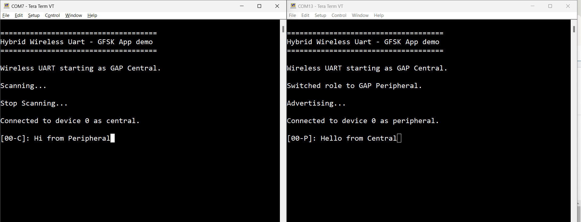
Parent topic:Usage
Case 2 (Generic FSK)
When operating the Generic FSK mode, the following steps should be followed.
Open a serial port terminal and connect to the two boards, in the same manner described in Testing devices. The start screen after the board is reset is the same as in Figure.
The Generic FSK communication direction is not preset. To start receiving, double click the SCANSW button on one board. Then, the device starts receiving packets on the same channel as the Bluetooth LE channel 37.
To start transmitting, long press the ROLESW button on the other board. The transmitting device uses an identifier known by the receiver and its packets are displayed in the CLI as shown in Figure:
Teraterm – packet transmit/receive on Generic FSK

To stop Generic FSK reception, double click the ROLESW button.
To stop the periodic Generic FSK transmit operation, long press the ROLESW button again, if the transmit procedure is ongoing. The long press of the ROLESW button acts as a toggle for the transmit. At this point, both devices can reverse the direction of communication by following the exact same steps.
See Figure.
Tera Term – stop Generic FSK activity
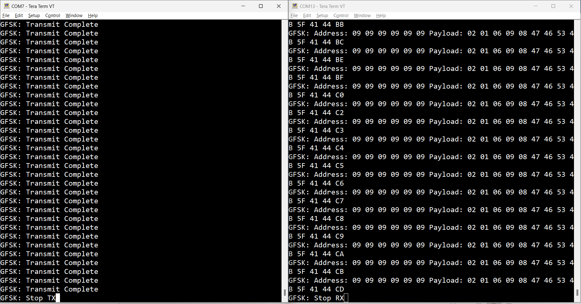
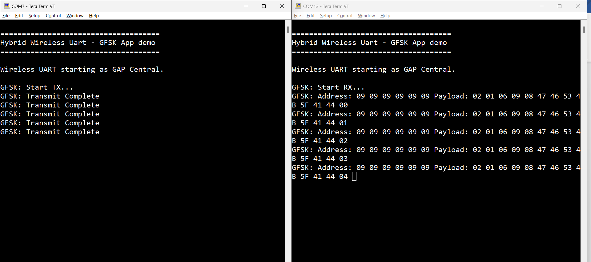
Parent topic:Usage
Case 3 (Dual-mode)
The application is ready to combine both scenarios. It can either:
Establish a Bluetooth LE connection and perform Generic FSK activity.
During Generic FSK activity, the Bluetooth LE connection can be established and the Controller pauses receiving or announcing the discarded Generic FSK transmissions. This activity is resumed after the Bluetooth LE activity is finished.
To run the Dual-mode scenario, follow the steps below:
Establish a Bluetooth LE connection as described in Case 1 (Bluetooth LE).
Start Generic FSK activity as described in Case 2 (Generic FSK), independent of the Bluetooth LE roles chosen in Case 1.
Start typing in either of the terminals. As seen in Figure, the Bluetooth LE activity is prioritized. In this step, characters are printed in the peer’s terminal and Generic FSK continues in the available slots, not used by the Bluetooth LE link.
Teraterm – Mixed Wireless UART (Bluetooth LE) and Generic FSK activity
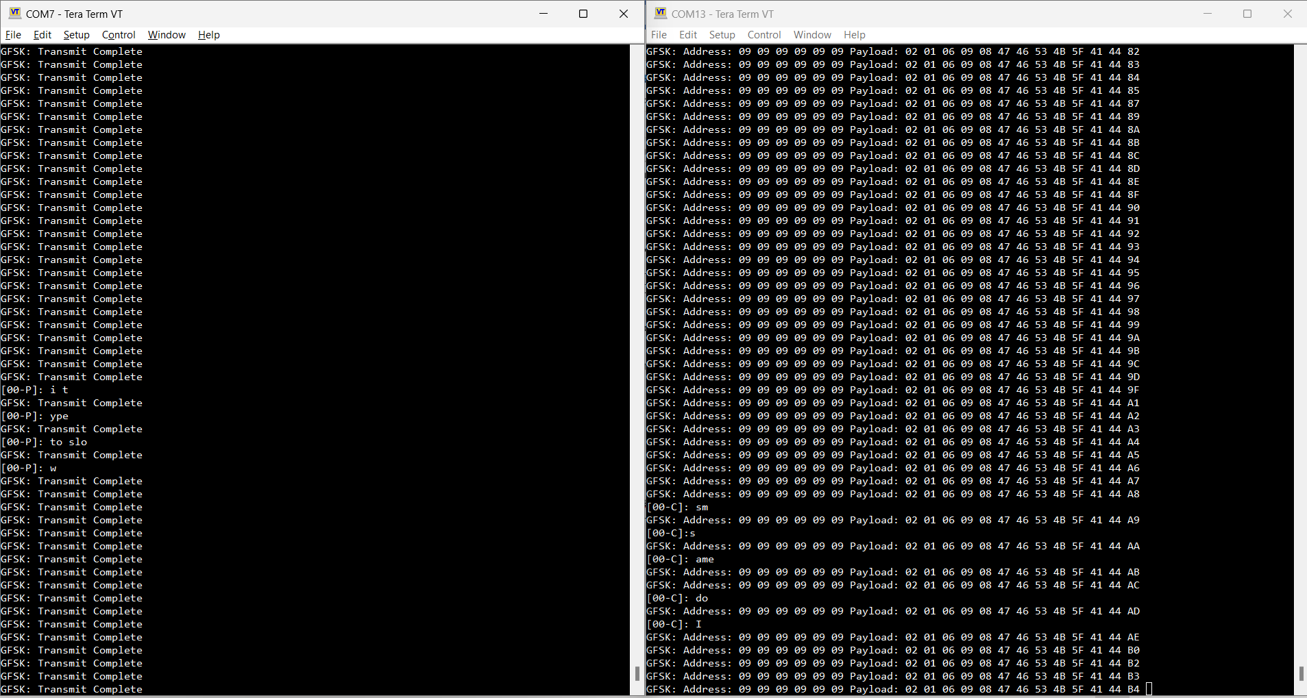
Parent topic:Usage
Parent topic:Hybrid (Dual-mode) Bluetooth Low Energy and Generic FSK
Customization
Use the steps below to change the default settings of this demo.
For Bluetooth LE, the default advertising config (gAdvParams) parameter is found in the app_config.c file. Also, the scanning parameters (gScanParams) can be found in this file.
The maximum number of connections supported by the Bluetooth LE, for this application, is defined in the app_preinclude.h file, with the macro name gAppMaxConnections_c.
Note: The Generic FSK protocol is active during the inactive periods of the Bluetooth LE protocol. The demo is currently configured to have the scan window equal to the scan interval to make the user aware of this, but this can be changed.
For Generic FSK, the following defines of interest can be found in genfsk_app.h, described below:
Name |
Description |
|---|---|
|
This is the network address used for the Generic FSK, in the transmitter payload. It is implicitly set to the 0x8E89BED6, but this can be reconfigured. Ensure that it is also changed on the receiver in the |
|
H0 value is used in the header. |
|
This is the identifier used by the transmitter to be filtered at the receiver. The current implementation filters the Generic FSK packets received, based on this define. |
|
This is the interval the transmitter will repeat the transmission of a packet. It is set in milliseconds. |
Files of interest
The demo can be found in the w_uart_genfsk from the available examples.
The demo is based on the basic Wireless UART with the addition of some Generic FSK files required for working in dual-mode, described below.
File name |
Description |
|---|---|
|
Application common module. Handles the HCI commands and events for the Generic FSK. Sends the events to the application. |
|
Application common module. Exposes public functions. |
|
Controller common module. Handles initialization of Generic FSK. |
|
Controller common module. Exposes public functions. |
Parent topic:Hybrid (Dual-mode) Bluetooth Low Energy and Generic FSK
Parent topic:Bluetooth LE stack and demo applications
Wireless UART Host
This section describes the implemented profiles and services, user interactions, and testing methods for the Wireless UART Host application.
The Wireless UART Host application is a demonstration of the Extended NBU architectural concept, where the Bluetooth LE Host Stack and the Link Layer both run on the NBU core, while the user-facing application runs on the Application core. The communication between the application and the Host is done via the FSCI protocol running on the inter-core RPMSG transport.
The Wireless UART Host application must be flashed together with the NCP FSCI Blackbox application.
Implemented profile and services
The Wireless UART Host application implements both the GATT client and server for the custom Wireless UART profile and services.
Wireless UART Service (UUID: 01ff0100-ba5e-f4ee-5ca1-eb1e5e4b1ce0)
Battery Service v1.0
Device Information Service v1.1
The Wireless UART service is a custom service that implements a custom writable ASCII Char characteristic (UUID: 01ff0101-ba5e-f4ee-5ca1-eb1e5e4b1ce0) that holds the character written by the peer device.
The application behaves at first as a GAP central node. It enters GAP Limited Discovery Procedure and searches for other Wireless UART devices to connect. To change the device role to GAP peripheral, use the ROLESW button. The device enters GAP General Discoverable Mode and waits for a GAP central node to connect.
Parent topic:Wireless UART Host
Supported platforms
The following platforms support the Wireless UART Host application:
MCX-W72-EVK
FRDM-MCXW72
Parent topic:Wireless UART Host
User interface
Ensure that both NCP FSCI Blackbox (for the NBU core) and Wireless UART Host (for the Application core) have been flashed to the board.
After flashing the board, the device is in idle mode (all LEDs flashing). To start scanning, press the SCANSW button. When in GAP Limited Discovery Procedure of GAP General Discoverable Mode, CONNLED is flashing. When the node connects to a peer device, CONNLED turns solid. To disconnect the node, hold the SCANSW button pressed for 2-3 seconds. The node then re-enters GAP Limited Discovery Procedure.
Parent topic:Wireless UART Host
Usage
The application is built to work with another supported platform running either Wireless UART or Wireless UART Host, or with the Wireless UART from the IoT Toolbox application.
When testing with two boards, perform the following steps:
Open a serial port terminal and connect to the two boards, in the same manner described in Testing devices. The start screen is blank after the board is reset.
The application starts as a GAP central. To switch the role to a GAP peripheral, press the role switch. Depending on the role, when pressing the SCANSW, the application starts either scanning or advertising.
As soon as the CONNLED turns solid on both devices, the user can start writing in one of the consoles. The text appears on the other terminal.
After creating a connection, the role (central or peripheral) is displayed on the console. The role switch can be pressed again before creating a new connection. See the figure below.
Tera Term – received text on Wireless UART
When testing with a single board and the IoT Toolbox, perform the following steps:
Open a serial port terminal and connect the board in the same manner described in Testing devices. The start screen is blank after the board is reset.
Press the role switch button to behave as a GAP peripheral and then press the SCANSW button to start advertising. The IoT Toolbox app can then connect. Select UART instead of Console and start typing, as shown in the Figure.
Parent topic:Wireless UART Host
Parent topic:Bluetooth LE stack and demo applications
FSCI Bridge
This section describes the functionality, user interactions, and testing methods for the FSCI Bridge demo application.
Description
The FSCI Bridge demo application is a demonstration of the Extended NBU architectural concept, where the Bluetooth LE Host Stack and the Link Layer both run on the NBU core, while the user-facing application runs on the Application core. The communication between the application and the Host is done via the FSCI protocol running on the inter-core RPMSG transport
The FSCI Bridge runs on the Application core and it is a simple application whose purpose is to pass FSCI commands received over the serial interface to the NCP FSCI Black Box running on the NBU core. Effectively, the functionality is identical to the regular Bluetooth FSCI Black Box application.
The demo can be used with the Test Tool for Connectivity Products - Command Console application which can be downloaded from the NXP website or using a custom application that supports the FSCI protocol and commands.
Parent topic:FSCI Bridge
Supported platforms
The following platforms support the FSCI Bridge application:
MCX-W72-EVK
FRDM-MCXW72
Parent topic:FSCI Bridge
Usage with Test Tool for connectivity products
The FSCI Bridge demo application is designed to be used via serial interface. This can be done using the TEST Tool for Connectivity Products – Command Console application as described below.
Download the FSCI Bridge application onto a supported board’s Application core, together with the NCP FSCI Black Box application on the NBU core.
Connect the board to a USB port of the PC. The USB COM port drivers must be installed properly and a COM port corresponding to the board should be available.
Open the Test Tool application and connect to the serial port corresponding to the board on which the FSCI Bridge application runs. See Figure. The serial communication parameters are: baud rate 115200, 8N1, and no flow control.
Select the appropriate Test Tool XML file from the drop-down list for the release being used and send commands to the application. An example is shown in Figure.
Parent topic:FSCI Bridge
Parent topic:Bluetooth LE stack and demo applications
NCP FSCI Black Box
This section describes the functionality of the NCP FSCI Black Box demo application.
Description
The NCP FSCI Black Box application is a demonstration of the Extended NBU architectural concept, where the Bluetooth LE Host Stack and the Link Layer both run on the NBU core, while the user-facing application runs on the Application core. The communication between the application and the Host is done via the FSCI protocol running on the inter-core RPMSG transport.
The NCP FSCI Black Box application runs on the NBU core and provides access to the Bluetooth LE Host Stack through FSCI to the application running on the Application core. It can be paired with the FSCI Bridge application to obtain a functionality that is identical to the regular Bluetooth FSCI Black Box application, or with the Wireless UART Host application to obtain a functionality that is identical to the regular Wireless UART application.
Parent topic:NCP FSCI Black Box
Supported platforms
The following platforms support the NCP FSCI Black Box application:
MCX-W72-EVK
FRDM-MCXW72
Parent topic:NCP FSCI Black Box
Parent topic:Bluetooth LE stack and demo applications