Functional description
Introduction
The following subsections describe the MCU bootloader functionality.
Parent topic:Functional description
Memory map
See MCU bootloader chapter of the reference manual of the particular System On Chip (SoC) for the ROM and RAM memory map used by the bootloader.
Parent topic:Functional description
MCU Bootloader Configuration Area (BCA)
The MCU bootloader reads data from the Bootloader Configuration Area (BCA) to configure various features of the bootloader. The BCA resides in flash memory at offset 0x3C0 from the beginning of the user application and provides all the parameters required to configure the bootloader operation. For uninitialized flash, the MCU bootloader uses a predefined default configuration. A host application can use the MCU bootloader to program the BCA for use during subsequent initializations of the bootloader.
Note: Flashloader does not support this feature.
Configuration Fields for the MCU bootloader
Offset |
Size (bytes) |
Configuration Field |
Description |
|---|---|---|---|
0x00 - 0x03 |
4 |
tag |
Magic number to verify bootloader configuration is valid. Must be set to ‘kcfg’. |
0x04 - 0x07 |
4 |
crcStartAddress |
Start address for application image CRC check. To generate the CRC, see the CRC chapter. |
0x08 - 0x0B |
4 |
crcByteCount |
Byte count for application image CRC check. |
0x0C - 0x0F |
4 |
crcExpectedValue |
Expected CRC value for application CRC check. |
0x10 |
1 |
enabledPeripherals |
Bitfield of peripherals to enable. |
0x11 |
1 |
i2cSlaveAddress |
If not 0xFF, used as the 7-bit I2C slave address. |
0x12 - 0x13 |
2 |
peripheralDetectionTimeout |
If not 0xFF, used as the timeout in milliseconds for active peripheral detection. |
0x14 - 0x15 |
2 |
usbVid |
Sets the USB Vendor ID reported by the device during enumeration. |
0x16- 0x17 |
2 |
usbPid |
Sets the USB Product ID reported by the device during enumeration. |
0x18 - 0x1B |
4 |
usbStringsPointer |
Sets the USB Strings reported by the device during enumeration. |
0x1C |
1 |
clockFlags |
Reserved.See clockFlags Configuration Field. |
0x1D |
1 |
clockDivider |
Reserved.Inverted value of the divider used for core and bus clocks when in high-speed mode. |
0x1E |
1 |
bootFlags |
One’s complement of direct boot flag. 0xFE represents direct boot. |
0x1F |
1 |
pad0 |
Reserved, set to 0xFF. |
0x20 - 0x23 |
4 |
mmcauConfigPointer |
Reserved, holds a pointer value to the MMCAU configuration. |
0x24 - 0x27 |
4 |
keyBlobPointer |
Reserved, holds a value to the key blob array used to configure OTFAD. |
0x28 |
1 |
pad1 |
Reserved. |
0x29 |
1 |
canConfig1 |
ClkSel[1], PropSeg[3], SpeedIndex[4] |
0x2A - 0x2B |
2 |
canConfig2 |
Pdiv[8], Pseg[3], Pseg2[3], rjw[2] |
0x2C - 0x2D |
2 |
canTxId |
txId |
0x2E - 0x2F |
2 |
canRxId |
rxId |
0x30 - 0x33 |
4 |
qspiConfigBlockPointer |
QuadSPI configuration block pointer |
The first configuration field ‘tag’ is a tag value or magic number. The bootloader configuration data is valid if the tag value is set to ‘kcfg’. If tag-field verification fails, the MCU bootloader acts as if the configuration data is not present. The tag value is treated as a character string, so bytes 0-3 must be set as shown in the table.
tag Configuration Field
Offset |
tag Byte Value |
|---|---|
0 |
‘k’ (0x6B) |
1 |
‘c’ (0x63) |
2 |
‘f’ (0x66) |
3 |
‘g’ (0x67) |
The flags in the clockFlags configuration field are enabled if the corresponding bit is cleared (0).
clockFlags Configuration Field
Bit |
Flag |
Description |
|---|---|---|
0 |
HighSpeed |
Enable high-speed mode (i.e., 48 MHz). |
1 - 7 |
- |
Reserved. |
Parent topic:Functional description
Start-up process
It is important to note that the startup process for bootloader in ROM, RAM (flashloader), and flash (flash-resident) are slightly different. See the chip-specific reference manual for understanding the startup process for the ROM bootloader and flashloader. This section focuses on the flash-resident bootloader startup only.
There are two ways to get into the flash-resident bootloader.
If the vector table at the start of internal flash holds a valid PC and SP, the hardware boots into the bootloader.
A user application running on flash or RAM calls into the MCU bootloader entry point address in flash to start the MCU bootloader execution.
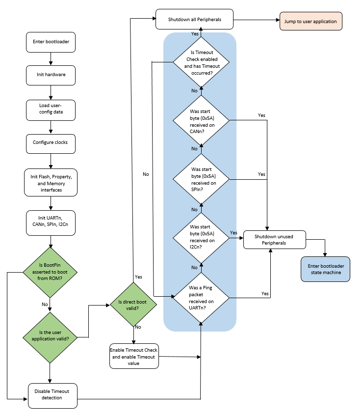
After the MCU bootloader has started, the following procedure starts the bootloader operations:
Initializes the bootloader .data and .bss sections.
Reads the bootloader configuration data from flash at offset 0x3C0. The configuration data is only used if the tag field is set to the expected ‘kcfg’ value. If the tag is incorrect, the configuration values are set to default, as if the data was all 0xFF bytes.
Clocks are configured.
Enabled peripherals are initialized.
The the bootloader waits for communication to begin on a peripheral.
If detection times out, the bootloader jumps to the user application in flash if the valid PC and SP addresses are specified in the application vector table.
If communication is detected, all inactive peripherals are shut down, and the command phase is entered.
MCU bootloader start-up flowchart
Parent topic:Functional description
Clock configuration
The clock configuration used by the bootloader depends on the clock settings in the bootloader configuration area and the requirements of the enabled peripherals. The bootloader starts by using the default clock configuration of the part out of reset.
Alternate clock configurations are supported by setting fields in the bootloader configuration data.
If the HighSpeed flag of the clockFlags configuration value is cleared, the core and bus clock frequencies are determined by the clockDivider configuration value.
The core clock divider is set directly from the inverted value of clockDivider, unless a USB peripheral is enabled. If a USB peripheral is enabled and clockDivider is greater than 2, clockDivider is reduced to 2 in order to keep the CPU clock above 20 MHz.
The bus clock divider is set to 1, unless the resulting bus clock frequency is greater than the maximum supported value. In this instance, the bus clock divider is increased until the bus clock frequency is at or below the maximum.
The flash clock divider is set to 1, unless the resulting flash clock frequency is greater than the maximum supported value. In this instance, the flash clock divider is increased until the flash clock frequency is at or below the maximum.
If flex bus is available, the flex bus clock divider is set to 1, unless the resulting flex bus clock frequency is greater than the maximum supported value. In this instance, the flex bus clock divider is increased until the flex bus clock frequency is at or below the maximum.
If a USB peripheral is enabled, the IRC48Mhz clock is selected as the USB peripheral clock and the clock recovery feature is enabled.
Note that the maximum baud rate of serial peripherals is related to the core and bus clock frequencies.
Note that the bootloader code does not always configure the device core clock to run at 48 MHz. For devices with no USB peripheral and when HighSpeed flag is not enabled in the BCA, the core clock is configured to run at default clock rate (i.e., 20.9 MHz). This is also true for devices with USB but HighSpeed flag is not enabled in the BCA.
Parent topic:Functional description
Bootloader entry point
The MCU bootloader provides a function (runBootloader) that a user application can call, to run the bootloader.
Note: Flashloader does not support this feature.
To get the address of the entry point, the user application reads the word containing the pointer to the bootloader API tree at offset 0x1C of the bootloader’s vector table. The vector table is placed at the base of the bootloader’s address range.
The bootloader API tree is a structure that contains pointers to other structures, which have the function and data addresses for the bootloader. The bootloader entry point is always the first word of the API tree.
The prototype of the entry point is:
void run_bootloader(void * arg);
The arg parameter is currently unused, and intended for future expansion. For example, passing options to the bootloader. To ensure future compatibility, a value of NULL should be passed for arg.
Example code to get the entry pointer address from the ROM and start the bootloader:
// Variables
uint32_t runBootloaderAddress;
void (*runBootloader)(void * arg);
// Read the function address from the ROM API tree.
runBootloaderAddress = **(uint32_t **)(0x1c00001c);
runBootloader = (void (*)(void * arg))runBootloaderAddress;
// Start the bootloader.
runBootloader(NULL);
Note: The user application must be executing at Supervisor (Privileged) level when calling the bootloader entry point.
Parent topic:Functional description
Application integrity check
The application integrity check is an important step in the boot process. The MCU bootloader provides an option, and when enabled, does not allow the application code to execute on the device unless it passes the integrity check.
MCU bootloader uses CRC-32 as its integrity checker algorithm. To properly configure this feature, the following fields in the BCA must be set to valid values:
Set crcStartAddress to the start address that should be used for the CRC check. This is generally the start address of the application image, where it resides in the flash or QuadSPI memory.
Set crcByteCount to the number of bytes to run the CRC check from the start address. This is generally the length of the application image in bytes.
Set crcExpectedValue to the checksum. This is the pre-calculated value of the checksum stored in the BCA for the bootloader to compare with the resultant CRC calculation. If the resultant value matches with the crcExpectedValue, then the application image passes the CRC check.
Note: See Section 2.3, “The MCU Bootloader Configuration Area (BCA)”, in the MCU Bootloader Reference Manual (document MCUBOOTRM) for details about the BCA.
MCU bootloader flow with integrity checker
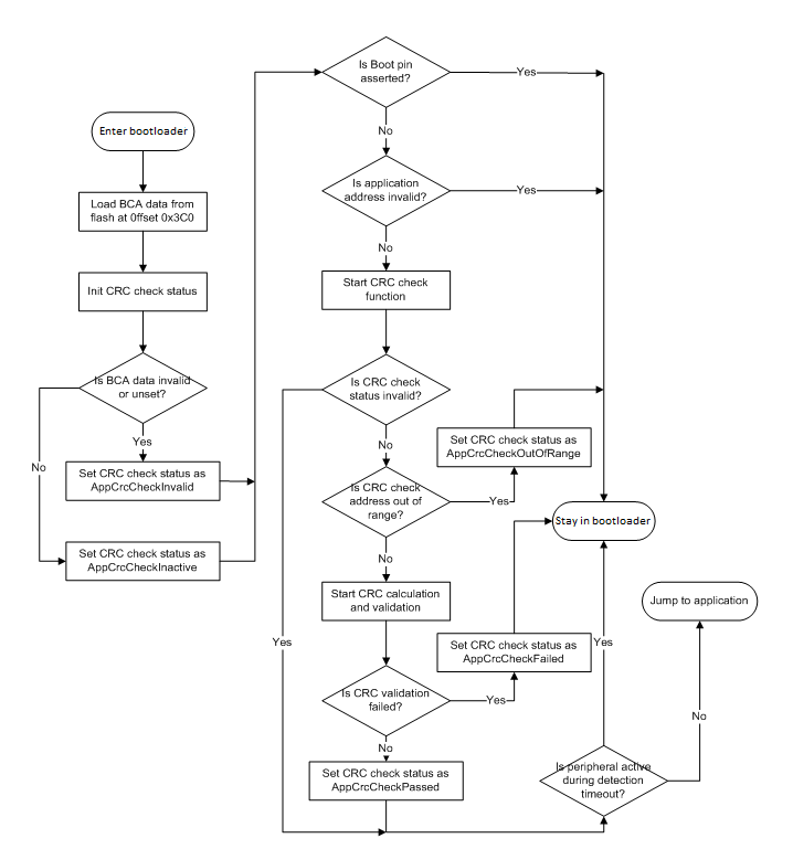
The following steps describe the flow of execution of the MCU bootloader when integrity check is enabled in the BCA.
Bootloader initialization
Load BCA data from flash at offset, corresponding to the application image start address + 0x3C0.
Initialize the CRC check status. If BCA is invalid (the tag is not set to expected ‘kcfg’ value), or the CRC parameters in valid BCA are not set, then the CRC check status is set to kStatus_AppCrcCheckInvalid, meaning the integrity check is not enabled for the device. Otherwise, the CRC check status is set to kStatus_AppCrcCheckInactive, meaning the integrity check is due for the device.
If a boot pin is not asserted and application address is a valid address (the address is not null, the address resides in a valid executable memory range, and the flash is not blank), then the bootloader begins the CRC check function. Otherwise, the CRC check function is bypassed.
The CRC check function. The bootloader checks the CRC check status initialized in the previous steps, and if it is not kStatus_AppCrcCheckInvalid (integrity check is enabled for the device), then the bootloader verifies the application resides in internal flash or external QSPI flash.
If the application address range is invalid, then the bootloader sets the status to kStatus_AppCrcCheckOutOfRange.
If the application address range is valid, then the CRC check process begins. If the CRC check passes, then the bootloader sets the status to kStatus_AppCrcCheckPassed. Otherwise, the status is set to kStatus_AppCrcCheckFailed.
Parent topic:MCU bootloader flow with integrity checker
Staying in or leaving bootloader
If no active peripheral is found before the end of the detection, the timeout period expires, and the current CRC check status is either set to kStatus_AppCrcCheckInvalid (integrity check is not enabled for the device), or kStatus_AppCrcCheckPassed. Then, the bootloader jumps to the application image. Otherwise, the bootloader enters the active state and wait for commands from the host.
Application integrity check flow
The following table provides the CRC algorithm which is used for the application integrity check. The CRC algorithm is the MPEG2 variant of CRC-32.
The characteristics of the MPEG2 variant are:
MPEG2 variant characteristics
Width |
32 |
|---|---|
Polynomial |
0x04C11BD7 |
Init Value |
0xFFFFFFFF |
Reflect In |
FALSE |
Reflect Out |
FALSE |
XOR Out |
0x00000000 |
The bootloader computes the CRC over each byte in the application range specified in the BCA, excluding the crcExpectedValue field in the BCA. In addition, MCU bootloader automatically pads the extra byte(s) with zero(s) to finalize CRC calculation if the length of the image is not 4-bytes aligned.
The following procedure shows the steps in CRC calculation.
CRC initialization
Set the initial CRC as 0xFFFFFFFF, which clears the CRC byte count to 0.
CRC calculation
Check if the crcExpectedValue field in BCA resides in the address range specified for CRC calculation.
If the crcExpectedValue does not reside in the address range, then compute CRC over every byte value in the address range.
If the crcExpectedValue does reside in the address range, then split the address range into two parts, splitting at the address of crcExpectedValue field in BCA excluding crcExpectedValue. Then, compute the CRC on the two parts.
Adjust the CRC byte count according to the actual bytes computed.
CRC finalization
Check if the CRC byte count is not 4-bytes aligned. If it is 4-bytes aligned, then pad it with necessary zeroes to finalize the CRC. Otherwise, return the current computed CRC.
Note: MCU bootloader assumes that crcExpectedValue field (4 bytes) resides in the CRC address range completely if it borders on the CRC address range.
Parent topic:MCU bootloader flow with integrity checker
Parent topic:Application integrity check
Parent topic:Functional description