MCU bootloader porting
Introduction
This chapter discusses the steps required to port an existing MCU bootloader to a new device. Each step of the porting process is discussed in detail in the following sections.
Parent topic:MCU bootloader porting
Choosing a starting point
The first step is to download the latest bootloader release. Updates for the bootloader are released multiple times per year, so having the latest package is important for finding the best starting point for your port. To find the most recent bootloader release, click on mcuxpresso.nxp.com, select middleware mcu-boot when configuring the sdk package. MCU Bootloader projects can be found in <sdk_package>/boards/<board>/bootloader_examples.
The easiest way to port the bootloader is to choose a supported target that is the closest match to the desired target device.
Note: Just because a supported device has a similar part number to the desired target device, it may not necessarily be the best starting point. To determine the best match, refer to the data sheet and reference manual for all of the supported MCU devices.
Parent topic:MCU bootloader porting
Preliminary porting tasks
All references to paths in the rest of this chapter are relative to the root of the extracted SDK package. MCU Bootloader is a middleware in SDK package loacted at middleware/ mcu-boot. Before modifying source code, the following tasks should be performed.
Download MCUXpresso SDK
Porting the MCU bootloader to a new target is a manual process that requires updating the device header files. This process is time-consuming and error-prone, so NXP provides Software Development Kit (SDK) for ARM Cortex-M Core devices. SDK package contains device header files and drivers. These SDK packages can be downloaded from mcuxpresso.nxp.com.
Note: Do not proceed with a port if a package does not yet exist for the desired target device.
In the downloaded package, header files including <device>.h, <device>_features.h, fsl_device_registers, system_<device>.h can be found in devices/<device>, and drivers can be found in devices/<device>/drivers. Add these two folders to include directories of the target device’s bootloader project or add these header files and drivers to the target device’s bootloader project.
Parent topic:Preliminary porting tasks
Copy the closest match
Copy the folder of the device that most closely matches the target device in the /middleware/mcu-boot/targets folder of the bootloader source tree. Rename the folder to match the target device part number.
After the files are copied, browse the newly created folder. Rename all files that have reference to the device from which they were copied. Rename the following files:
clock_config_<old_device>.c —> clock_config_<new_device>.c
hardware_init_<old_device>.c —> hardware_init _<new_device>.c
memory_map_<old_device>.c —> memory_map _<new_device>.c
peripherals_<old_device>.c —> peripherals _<new_device>.c
Copy the following files from their location in devices/<device>/<tool chain> to the new middleware/mcu-boot/targets/<device>/src/startup folder:
<tool chain>/startup_<device>.s
Parent topic:Preliminary porting tasks
Provide device startup file (vector table)
A device-specific startup file is a key piece to the port. The bootloader may not function correctly without the correct vector table. A startup file from the closest match device can be used as a reference, but it is strongly recommended that the file be thoroughly checked before using it to port due to differences in interrupt vector mappings between devices.
Create the startup file and place into the middleware/mcu-boot/targets/<device>/src/startup/<tool chain> folder. Startup files are often assembly (*.s) and are named startup_<device>.s.
Note: For Kinetis devices, the 16-byte Flash Configuration Field should be carefully set in the bootloader image. The Flash Configuration Field is placed at the offset 0x400 in the bootloader image. The field is documented in the SOC reference manual under the subsection called, “Flash Configuration Field” in the “Flash Memory Module” chapter. To change the default 16-byte value for the field in the template startup_<device>.s file of the bootloader project, follow these steps:
Open the startup_<device>.s file in a text editor.
Locate the symbol where Flash Configuration Field is specified. The symbol name is “__FlashConfig” The 16-byte Flash Configuration Field data is enclosed with __FlashConfig and __FlashConfig_End symbols in the startup_<device>.s file
Change the 16-byte setting to the correct value. For example set the flash security byte, enable or disable backdoor access key, specify the 8-byte backdoor key, and so on.
Once the field is updated, save the startup_<device>.s file and close the text editor.
Parent topic:Preliminary porting tasks
Clean up the IAR project
This example uses the IAR tool chain for the new project. Other supported tool chains can be used in a similar manner.
MCU Bootloader projects can be found in <boards>/board/bootloader_examples. Open a bootloader project of the most similar device. This image shows an example of what a workspace looks like and the files that need to be touched.
IAR workspace
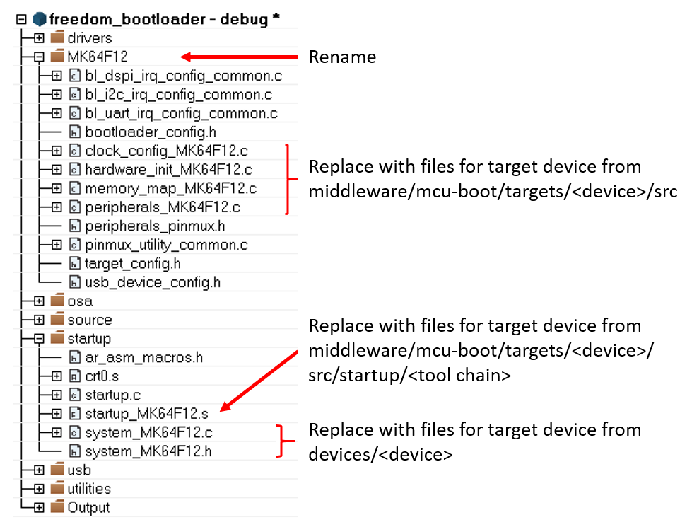
Once changes have been made, update the project to reference the target device. This can be found in the project options.
Project options
|
|
Parent topic:Preliminary porting tasks
Bootloader peripherals
There are two steps required to enable and configure the desired peripherals on the target device:
Choose which peripherals can be used by the bootloader.
Configure the hardware at a low level to enable access to those peripherals.
Parent topic:Preliminary porting tasks
Parent topic:MCU bootloader porting
Primary porting tasks
After the basic file structure and source files are in place, the porting work can begin. This section describes which files need to be modified and how to modify them.
Bootloader peripherals
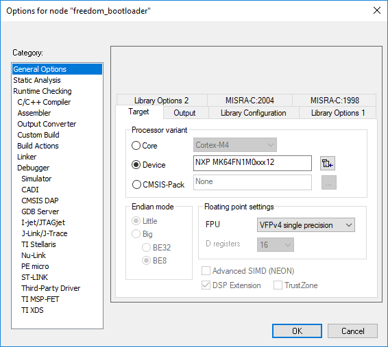
The bootloader source uses a C/C++ preprocessor define to configure the bootloader based on the target device. Update this define to reference the correct set of device-specific header files.
Options for node “freedom_bootloader” 
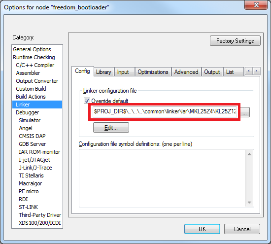
If the memory configuration of the target device differs from the closest match, the linker file must be replaced. Refer to linker files in devices/<device>/<tool chain> and update it as per the bootloader project. Update the linker settings via the project options.
Porting guide change linker file
Supported peripherals
The bootloader uses the peripherals_<device>.c file to define which peripheral interfaces are active in the bootloader. The source file includes a single table, g_peripherals[], that contains active peripheral information and pointers to configuration structures. This file is found in middleware/mcu-boot/targets/<device>/src.
Only place configurations for peripherals that are present on the target device. Otherwise, the processor generates fault conditions when trying to initialize a peripheral that is not physically present.
For the content of each entry in the g_peripherals[] table, reuse existing entries and only modify the .instance member. For example, starting with the following UART0 member, make the change to UART1 by simply changing .instance from “0” to “1”.
{
      .typeMask = kPeripheralType_UART,
      .instance = 0,
      .pinmuxConfig = uart_pinmux_config,
      .controlInterface = &g_scuartControlInterface;
      .byteInterface = &g_scuartByteInterfacek;
      .packetInterface = &g_framingPacketInterface;
}
When the table has all required entries, it must be terminated with a null { 0 } entry.
Parent topic:Bootloader peripherals
Peripheral initialization
After the peripheral configuration has been selected, the low-level initialization must be accounted for. The bootloader automatically enables the clock and configures the peripheral, so the only thing required for the port is to tell the bootloader which pins to use for each peripheral. This is handled in the peripherals_pinmux.h file in middleware/ mcu-boot/targets/<device>/src. The hardware_init_<device>.c file selects the boot pin used by the bootloader, which may need to be changed for the new target device.
These files most likely require significant changes to account for the differences between devices when it comes to pin routing. Each function should be checked for correctness and modified as needed.
Parent topic:Bootloader peripherals
Clock initialization
The MCU bootloader typically uses the device default clock configuration in order to avoid dependencies on external components and simplify use. In some situations, the default clock configuration cannot be used due to accuracy requirements of supported peripherals. On devices that have on-chip USB and CAN, the default system configuration is not suficient and the bootloader configures the device to run from the high-precision internal reference clock (IRC) if available. Otherwise, it depends on the external oscillator supply.
The bootloader uses the clock_config_<device>.c file in middleware/mcu-boot/targets/ <device>/src to override the default clock behavior. If the port’s target device supports USB, this file can be used. If the port’s target device does not support USB, the functions within clock_config_<device>.c can be stubbed out or set to the required port value.
Parent topic:Bootloader peripherals
Parent topic:Primary porting tasks
Bootloader configuration
Configure the bootloader to match the supported features and the specific memory map for the target device. Turn features on or off by using #define statements in the bootloader_config.h file in middleware/mcu-boot/targets/<device>/src. See examples for using these macros in bl_command.c (g_commandHandlerTable[] table) in the middleware/mcu-boot/src/bootloader/src folder. All checks that reference a BL_* feature can be turned on or off. Examples of these features are BL_MIN_PROFILE, BL_HAS_MASS_ERASE, and BL_FEATURE_READ_MEMORY.
One of the most important bootloader configuration choices is where to set the start address (vector table) of the user application. This is determined by the BL_APP_VECTOR_TABLE_ADDRESS define in bootloader_config.h. Most bootloader configurations choose to place the user application at address 0xA000 because that accommodates the full-featured bootloader image. It is possible to move this start address if the resulting port reduces features (and therefore, code size) of the bootloader.
Note: Load the Release build of the flash-resident bootloader if you plan to place the user application at 0xA000. Loading the Debug build requires you to move the application address beyond the end of the bootloader image. This address can be determined from the bootloader map file.
Parent topic:Primary porting tasks
Bootloader memory map configuration
The MCU device memory map and flash configuration must be defined for proper operation of the bootloader. The device memory map is defined in the g_memoryMap[] structure of the memory_map_<device>.c file, which can be found in middleware/mcu-boot/targets/<device>/src. An example memory map configuration is shown.
memory_map_entry_t g_memoryMap[] =
{
    {0x00000000,0x000fffff, kMemoryIsExecutable, &g_flashMemoryInterface},   // Flash array (1024KB)
    {0x1fff0000,0x2002ffff, kMemoryIsExecutable, &g_normalMemoryInterface},  // SRAM (256KB)
    {0x40000000,0x4007ffff, kMemoryNotExecutable, &g_deviceMemoryInterface},// AIPS peripherals
    {0x400ff000,0x400fffff, kMemoryNotExecutable, &g_deviceMemoryInterface}, // GPIO
    {0xe0000000,0xe00fffff, kMemoryNotExecutable, &g_deviceMemoryInterface},// M4 private peripherals
    {0}                                                                                                                    // Terminator
};
In addition to the device memory map, the correct SRAM initialization file must be selected according to the target device. This file is split based on ARM® Cortex®-M4 and Cortex-M0+ based devices, so the likelihood of having to change it is low.
The sram_init_cm4.c file is located in middleware/mcu-boot/src/memory/src for M4 devices and sram_init_cm0plus.c for M0+ devices.
Parent topic:Primary porting tasks
Parent topic:MCU bootloader porting