Network routing
The basic operation of a network is to transfer data from one node to another. The data is sourced from an input (possibly a switch or a sensor) on the originating node, and is communicated to another node which can interpret and use the data.
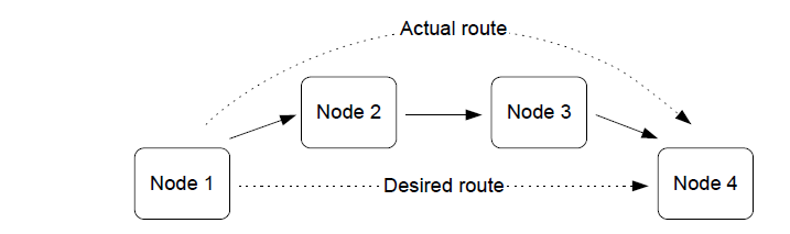
In the simplest data communication, the data is transmitted directly from the source node to the destination node. However, if the two nodes are far apart or in a difficult environment, direct communication may not be possible. In this case, it is necessary to send the data to another node within radio range, which then passes it on to another node, and so on until the desired destination node is reached - that is, to use one or more intermediate nodes as stepping stones. The process of receiving data destined for another node and passing it on is known as routing.
Message routing
Routing allows the range of a network to be extended beyond the distances supported by direct radio communication. Remote devices can join the network by connecting to a Router.
Note: Application programs in intermediate nodes are not aware of the relayed message or its contents - the relaying mechanism is handled by the ZigBee stack.
Message addressing and propagation
If a message sent from one node to another needs to pass through one or more intermediate nodes to reach its final destination (up to 30 such hops are allowed), the message carries two destination addresses:
Address of the final destination.
Address of the node which is the next “hop”.
ZigBee PRO is designed for Mesh networks (see Section 3.2.2) in which the message propagation path (the route) depends on whether the target node is in radio range:
If the target node is in range, only the “final destination” address is used.
If the target node is not in range, the “next hop” address is that of the first node in the route to the final destination.
The “next hop” address is determined using information stored in a Routing table on the routing node (Router or Coordinator). An entry of this table contains information for a remote node, including the network addresses of the remote node and of the next routing node in the route to the remote node. Thus, when a message is received by a routing node, it looks for the destination address in its Routing table and extracts “next hop” address from this table to insert into the message. The message is then passed on and propagation continues in this way until the target node is reached.
Note: If the message originates from an End Device, the message is always first passed to the source node’s parent before being passed on.
Parent topic:Network routing
Route discovery
The ZigBee stack network layer supports a ‘route discovery’ facility which finds the best available route to the destination, when sending a message. A message is normally routed along an already discovered mesh route, if one exists. Otherwise, the routing node (Router or the Coordinator) involved in sending the message initiates a route discovery. Once complete, the message is sent along the calculated route.
The mechanism for route discovery between two End Devices has the following steps:
A route discovery broadcast is sent by the parent of the source End Device, and contains the destination End Device’s network address.
All routing nodes eventually receive the broadcast, one of which is the parent of the destination End Device.
The parent of the destination node sends back a reply addressed to the parent of the source node.
As the reply travels back through the network, the hop count and a signal quality measure for each hop are recorded. Each routing node in the path can build a Routing table entry containing the best path to the destination End Device.
The best path is usually the one with the least number of hops. However, if a hop on the most direct route has a poor signal quality, a greater chance that retries would be needed. In such cases, a route with more hops might be chosen.
Eventually each routing node in the path has a Routing table entry and the route from source to destination End Device is established. Note that the corresponding route from destination to source is not known - the route discovered is unidirectional.
A source Router implements route discovery in a similar way to the above except the Router broadcasts its own route discovery message (without needing its parent to do this). Similarly, the Coordinator broadcasts its own route discovery messages.
Note:
Message routing is performed automatically by the ZigBee stack and is transparent to the user application. If required, route discovery is also automatic and transparent to the application.
Parent topic:Network routing
‘Many-to-one’ routing
A common scenario in a wireless network is the need for most network nodes to communicate with a single node that performs some centralized function, for example, a gateway. This node is often referred to as a concentrator.
In order to establish communication with the concentrator, each remote node may initiate a ‘route discovery’, resulting in a corresponding entry in the Routing table of each routing node along the way. If most network nodes need to communicate with the concentrator, many such route discoveries may be initiated. Where the resulting routes have a common leg, the relevant Routing table entries will not be duplicated but shared. However, a large number of simultaneous route discoveries may require significant memory space in the nodes near the concentrator for the temporary storage of route discovery information, and possibly result in memory overflow and traffic congestion.
A more efficient method of establishing routes to a concentrator is for the concentrator to initiate a ‘many-to-one’ route discovery for routes from all other network nodes to itself. To do this, the concentrator broadcasts a route discovery request and the Routing tables are updated as the broadcast propagates through the network. Since no responses are generated, the temporary storage of route discovery information is not required and network traffic congestion is minimized.
Many-to-one route discovery is illustrated in the figure below.
‘Many to one’ routing

In order to avoid the storage of return routes (from the concentrator) in the Routing tables of intermediate nodes, the technique of source routing is used - the outward route taken by a message to the concentrator is remembered by the concentrator and embedded in the response message. In this case, the response message must carry up to 30 addresses of the nodes along the return route (maximum number of hops allowed is 30).
Parent topic:Network routing
Parent topic:ZigBee PRO architecture and operation