ZigBee PRO architecture and operation
This chapter introduces ZigBee PRO from architectural and operational view-points by describing:
Basic architecture on which ZigBee PRO is based. See Section 3.1, (Architectural overview)
Concepts for an understanding of ZigBee PRO at the network level. See Section 3.2 (Network level concepts)
Process of network formation. See Section 3.3, (Network creation)
Concepts for an understanding of ZigBee PRO at the application level. See Section 3.4, (Application level concepts)
Features and concepts related to message routing. See Section 3.5, (Network routing)
Features and concepts related to exchanging messages. See Section 3.6, (Network communications)
A detailed view of the ZigBee PRO software architecture. See Section 3.7, (Detailed architecture)
Architectural overview
This section introduces the basic architecture of the software that runs on a ZigBee PRO network node. The software architecture is built on top of IEEE 802.15.4, an established and proven standard for wireless communication.
From a high-level view, the software architecture of any ZigBee network consists of four basic stack layers: Application layer, Network layer, Data Link layer and Physical layer. The Application layer is the highest level and the Physical layer is the lowest level, as illustrated in the figure below.
Basic software architecture

The basic layers of the ZigBee software stack are described below, from top to bottom:
Application layer: The Application layer contains the applications that run on the network node. These give the device its functionality - essentially an application converts input into digital data, and/or converts digital data into output. A single node may run several applications - for example, an environmental sensor may contain separate applications to measure temperature, humidity and atmospheric pressure.
Network layer: The Network layer provides the ZigBee PRO functionality and the application’s interface to the IEEE 802.15.4 layers. The layer is concerned with network structure and multi-hop routing.
Data Link layer: The Data Link layer is provided by the IEEE 802.15.4 standard and is responsible for addressing - for outgoing data it determines where the data is going, and for incoming data it determines where the data has come from. It is also responsible for assembling data packets or frames to be transmitted and disassembling received frames. In the IEEE 802.15.4 standard, the Data Link layer is referred to as IEEE 802.15.4 MAC (Media Access Control) and the frames used are MAC frames.
Physical layer: The Physical layer is provided by the IEEE 802.15.4 standard and is concerned with the interface to the physical transmission medium (radio, in this case). It is facilitates exchange of data bits with this medium, as well as with the layer above (the Data Link layer). In the IEEE 802.15.4 standard, the Physical layer is referred to as IEEE 802.15.4 PHY.
For a more detailed view of the software architecture of ZigBee PRO, refer to Section 3.7, Detailed architecture.
Note: Security measures are implemented throughout the stack, including the Application layer and lower stack layers.
Parent topic:ZigBee PRO architecture and operation
Network level concepts
This section describes important concepts relating to the work of the ZigBee stack.
ZigBee nodes
There are three general types of node that can exist in a ZigBee network:
Coordinator
Router
End Device
Note: These roles exist at the network level - a ZigBee node may also be performing tasks at the Application level, independent of the role it plays in the network.
For example, a network of ZigBee devices measuring temperature may have a temperature sensor application in each node, irrespective of whether the node is an End Device, Router, or the Coordinator.
The roles of these node types are described in the sub-sections below.
Coordinator
All ZigBee networks must have one (and only one) Coordinator.
At the network level, the Coordinator is mainly needed at system initialization - it is the first node to be started and performs the following initialization tasks:
Selects the frequency channel to be used by the network (usually the one with the least detected activity)
Starts the network
Allows child nodes to join the network through it
The Coordinator can additionally provide other services such as message routing and security management. It may also provide services at the Application level. If any of these additional services are used, the Coordinator must be able to provide them at all times. However, if none of these additional services are used, the network will be able to operate normally even if the Coordinator fails or is switched off.
Parent topic:ZigBee nodes
Router
A ZigBee PRO network usually has at least one Router. The main tasks of a Router are:
Relays messages from one node to another.
Allows child nodes to join the network through it.
Note: An important feature of the Router is that it cannot sleep, as it must always be available for routing.
Parent topic:ZigBee nodes
End Device
The main task of an End Device at the network level is sending and receiving messages. An End Device can only communicate directly with its parent, so all messages to/from an End Device pass via its parent.
An End Device can be battery-powered and, when not transmitting or receiving, can sleep in order to conserve power. The parent device buffers messages destined for a sleep-enabled End Device. The End Device collects these messages once it is awake (also see Section 3.2.2 Network topology below).
Note: End Devices cannot relay messages and cannot allow other nodes to connect to the network through them. In other words, it implies that they cannot have children.
Parent topic:ZigBee nodes
Parent topic:Network level concepts
Network topology
The ZigBee PRO standard was designed to facilitate wireless networks with the Mesh topology.
A Mesh network consists of a Coordinator, Routers, and End Devices. The Coordinator is associated with a set of Routers and End Devices - its children. A Router may then be associated with more Routers and End Devices - its children. This can continue to a number of levels. The relationships between the nodes must obey the following rules:
The Coordinator and Routers can have children, and can therefore be parents.
A Router can be both a child and a parent.
End Devices cannot have children, and therefore cannot be parents. The communication rules for a Mesh network are as follows:
An End Device can only directly communicate with its parent (and with no other node).
A Router can directly communicate with its children, with its own parent, and with any other Router or Coordinator within radio range.
The Coordinator can directly communicate with its children and with any Router within radio range.
The resulting structure is illustrated in the figure below.
Mesh topology

In ZigBee PRO, the maximum depth (number of levels below the Coordinator) of a network is 15. The maximum number of hops that a message can make in traveling between the source and destination nodes is 30 (twice the maximum depth).
A routing node (Router or Coordinator) can communicate directly with other routing nodes within radio range. This specific property distinguishes a Mesh network from a Tree network. This property enables very efficient and flexible message propagation. It also implies that alternative routes can be found if a link fails or there is congestion.
Note: An End Device, which is able to sleep, is unable to receive messages directly. A message destined for a sleep-enabled End Device is always buffered in its parent node if the End Device is asleep when the message arrives. Once the End Device is awake, it must ask or ‘poll’ the parent for messages. In the Mesh topology, a ‘route discovery’ feature is provided, which allows the network to find the best available route for a message. Refer further details in Section 3.5.2, “Route discovery”.
Note: Message propagation is handled by the network layer software and is transparent to the application programs running on the nodes.
Parent topic:Network level concepts
Neighbor tables
A routing node (Router or Coordinator) holds information about its neighboring nodes. This information is stored in a Neighbor table containing entries for the node’s immediate children, for its own parent and, in a Mesh network, for all peer Routers with which the node has direct radio communication.
It is possible to define the maximum number of entries in a Neighbor table. If this parameter is set to a low value, it will result in a ‘long, thin network’.
The structure and configuration of a Neighbor table are described in Appendix B.5.1.
Parent topic:Network level concepts
Network addressing
In a ZigBee network, each node must have a unique identification. For this purpose, each node has two addresses:
IEEE (MAC) address: A 64-bit address, allocated by the IEEE, which uniquely identifies the device. No two devices in the world can have the same IEEE address. It is often referred to as the MAC address. In a ZigBee network, it is sometimes called the ‘extended’ address.
Network address: A 16-bit address that identifies the node in the network and is local to that network. Thus, two nodes in separate networks may have the same network address. It is sometimes called the ‘short’ address.
In ZigBee PRO, the network address of a node is dynamically assigned as a random 16-bit value by the parent when the node first joins the network. This is known as stochastic addressing due to the randomness of the address allocation. Although random, the parent ensures that the chosen address has not already been assigned to one of its neighbors. In the unlikely event of the address already existing in the network beyond the immediate neighborhood, a mechanism exists to automatically detect and resolve the conflict. The allocated network address can be retained by the joining node, even if it later loses its parent and acquires a new parent.
The Coordinator always has the network address 0x0000.
While an application on a node may use IEEE/MAC addresses or network addresses to identify remote nodes, the ZigBee PRO stack always uses network addresses for this purpose. To facilitate translation between IEEE/MAC addresses and network addresses, an Address Map table may be maintained on the node, where each table entry contains the pair of addresses for a remote node.
In the NXP implementation of ZigBee PRO, the IEEE/MAC addresses (of other network nodes) are stored in a single place on a node, called the MAC Address table. This avoids the need to repeat the 64-bit IEEE/MAC addresses in other tables, such as the Address Map table and Neighbor table, and therefore saves storage space. Instead, a 16-bit index to the relevant entry in the MAC Address table is stored in the other tables.
It is also possible to define a 16-bit ‘group address’ which refers to a set of applications (or endpoints that may be located across several nodes. For details, refer to Section 3.4.1, Multiple applications and endpoints).
Specifying a group address in a data transfer results in the data being broadcast to all nodes in the network but, at the destinations, the data is only passed to those applications, which are covered by the group address. Refer to Section 6.3, Managing group addresses for more details of using group addresses.
Parent topic:Network level concepts
Network identity
A ZigBee network must be uniquely identifiable. This allows more than one ZigBee network to operate in close proximity - nodes operating in the same space must be able to identify which network they belong to.
For this purpose, ZigBee uses two identifiers, as follows:
PAN ID: A 16-bit value called the PAN ID (Personal Area Network Identifier) is used in inter-node communications (implemented at the IEEE 802.15.4 level of the stack) to identify the relevant network. A value for the PAN ID is selected at random by the Coordinator when the network is started. When other nodes join the network, they learn the network’s PAN ID and use it in all subsequent communications with the network.
It is possible that the PAN ID generated for a newly installed network clashes with the PAN ID of another network already operating on the same radio channel, in the same neighborhood. In this case, ZigBee PRO automatically resolves such a conflict by generating another random PAN ID for the new network. This continues until a value is obtained that does not clash with the PAN ID of any other detectable network.
Extended PAN ID: A 64-bit value called the Extended PAN ID (EPID) is used in forming the network and subsequently modifying the network, if necessary. This identifier can be pre-set to a random value in the user application that runs on the Coordinator. Alternatively, the identifier can be pre-set to zero. In this case, the Coordinator adopts its own 64-bit IEEE/MAC address as the Extended PAN ID when the network starts. This is a sure way of obtaining a globally unique value (see Section 3.2.4).
When a Router or End Device first tries to find a network to join, it uses the Extended PAN ID in either of following ways:
If an Extended PAN ID has been pre-set in the user application for the Router or End Device, the node joins the network that has this Extended PAN ID (provided this network is detected).
If there is no pre-set Extended PAN ID for the Router or End Device, the node joins the first network detected, irrespective of the Extended PAN ID. The joining node then learns the Extended PAN ID of its network. It later uses this identifier to rejoin the network if, for some reason, it loses contact with the network (the node is orphaned).
For more information on joining a network, refer to Section 3.3.2.
Note: At the Application level, you only need to be concerned with the Extended PAN ID, as the allocation and use of the PAN ID is transparent to the application.
Parent topic:Network level concepts
Parent topic:ZigBee PRO architecture and operation
Network creation
This section outlines the process of starting and forming a ZigBee PRO network:
Section 3.3.1 describes how the Coordinator starts a network.
Section 3.3.2 describes how a Router or End Device joins a network as part of the network formation process.
Note: The network formation actions described in this section are performed automatically by the ZigBee stack. The actions required at the application level are described later in Section 6.1, “Forming and Joining a Network”.
Starting a Network (Coordinator)
The Coordinator is responsible for starting a network. It must be the first node to be started and, once powered on, goes through the following network initialization steps:
Set EPID and Coordinator address
The Coordinator first sets the Extended PAN ID (EPID) for the network and the device’s own network address:
Sets the EPID to the 64-bit value specified in the Coordinator’s application (if this value is zero, the EPID will be set to the 64-bit IEEE/MAC address of the Coordinator device)
Sets the 16-bit network address of the Coordinator to 0x0000
Parent topic:Starting a Network (Coordinator)
Select radio channel
The Coordinator then selects the radio channel in which the network will operate, within the chosen RF band. The Coordinator performs an Energy Detection Scan in which it scans the RF band to find a quiet channel (the scan can be programmed to ‘listen’ to specific channels). The channel with the least detected activity is chosen.
Parent topic:Starting a Network (Coordinator)
Set the PAN ID of the network
Once the radio channel has been selected, the Coordinator chooses a 16-bit PAN ID for the network. To do this, it listens in the channel for traffic from other networks and identifies the PAN IDs of these networks (if any). To avoid conflicts, the Coordinator assigns its own network a random PAN ID that is not in use by another network.
Parent topic:Starting a Network (Coordinator)
Receive join requests from other devices
The Coordinator is now ready to receive requests from other devices (Routers and End Devices) to wirelessly connect to the network through it. For more information on joining a network, refer to Section 3.3.2.
Parent topic:Starting a Network (Coordinator)
Parent topic:Network creation
Joining a network (Routers and End Devices)
Routers and End Devices can join an existing network already created by a Coordinator. The Coordinator and Routers have the capability to allow other nodes to join the network through them. The join process is as follows:
Search for network
The new node first scans the channels of the relevant RF band to find a network. Multiple networks may operate, even in the same channel, and the selection of a network is the responsibility of the application (for example, this decision could be based on a pre-defined Extended PAN ID).
Parent topic:Joining a network (Routers and End Devices)
Select parent
The node now selects a parent node within the chosen network by listening to network activity. The node may be able to ‘hear’ multiple Routers and the Co- ordinator from the network. Given a choice of parents, the node chooses the parent with the smallest depth in the network - that is, the parent closest to the Coordinator (which is at depth zero).
Parent topic:Joining a network (Routers and End Devices)
Request joining
The node sends a message to the desired parent, asking to join the network.
Parent topic:Joining a network (Routers and End Devices)
Receive response
The node now waits for a response from the potential parent, which determines whether the node is a permitted device and whether the parent is currently allowing devices to join. To determine whether the joining node is a permitted device, the parent consults the Trust Centre (if it is not the Trust Centre itseIf). If these criteria are satisfied, the parent will then allow the node to join the network as its child. In its acceptance response to its new child, the parent will include the 16-bit network address that it has randomly allocated to the child (see Section 3.2.4).
If the potential parent is unable to accept the node as a child, a rejection response is sent. to the node, which must then try another potential parent (or another network).
Parent topic:Joining a network (Routers and End Devices)
Learn network IDs
The new node learns the PAN ID and Extended PAN ID of the network, as well as the network address that it has been assigned. It will need the PAN ID for communications with the network and will need the Extended PAN ID if, at some point in the future, it needs to rejoin the network (it will also be able to re- use its network address if it later rejoins the network).
A Router or Coordinator can be configured to have a time-period during which joins are allowed, controlled by its ‘permit joining’ status. The join period may be initiated by a user action, such as pressing a button. An infinite join period can also be set, so that child nodes can join the parent node at any time.
Note: When an orphaned node attempts to rejoin the network, the ‘permit joining’ status of a potential parent is ignored. Thus, the node is able to rejoin the network through a parent on which ‘permit joining’ is disabled.
Parent topic:Joining a network (Routers and End Devices)
Parent topic:Network creation
Parent topic:ZigBee PRO architecture and operation
Application level concepts
This section describes some key concepts required at the application level.
Multiple applications and endpoints
A node may have several applications running on it - for example, a node in a smart home network may incorporate an occupancy sensor and a light switch, each of which is an application. In fact, each application implements a ZigBee device type (see Section 2.10). Access to application instances is provided through endpoints, which act as communication ports for the applications.
In order to direct a message to the appropriate application instance on a node, the relevant endpoint must be specified. Endpoints are numbered from 1 to 240.
Therefore, to communicate with a remote application instance in a ZigBee network, you need to supply the address of the remote node together with the required endpoint number on the node.
Endpoint 255 is the broadcast endpoint number - the same data can be sent to all application instances on a node by sending the message to this endpoint number.
Parent topic:Application level concepts
Descriptors
An application may need to obtain information about the nodes of the network in which it runs, as described in Section 3.4.6. For this, it uses information stored in descriptors in the nodes.
There are three mandatory descriptors and two optional descriptors stored in a node. The mandatory descriptors are the Node, Node Power and Simple descriptors, while the optional descriptors are called the Complex and User descriptors
For each node, there is only one Node and Node Power descriptor, but there is a Simple descriptor for each endpoint. There may also be Complex and User descriptors in the device.
The Node, Node Power and Simple descriptors are outlined below. For full details of the descriptors, refer to Section 9.2.1.
Simple descriptor
The Simple descriptor for an application includes:
The endpoint on which the application runs and communicates
The ZigBee device type that the application implements
The ZigBee clusters that the device type implements
Whether there are corresponding Complex and User descriptors
Lists of input and output clusters (see Section 3.4.1) that the application uses and provides, respectively
Parent topic:Descriptors
Node descriptor
The Node descriptor contains information on the capabilities of the node, including:
Type (End Device, Router or Coordinator)
Frequency band in use (868 MHz, 902 MHz or 2400 MHz)
IEEE 802.15.4 MAC capabilities - that is, whether:
the device can be a PAN Coordinator
the node implements a Full-Function or Reduced-Function IEEE 802.15.4 device
the device is mains powered
the device is capable of using MAC security
the receiver stays on during idle periods
Manufacturer code
Stack compliance revision (of the ZigBee PRO Core specification to which the stack complies - prior to Revision 22/ZigBee2017, these bits were reserved and set to zero)
Maximum buffer size (the largest data packet that can be sent by an application in one operation)
Parent topic:Descriptors
Node power descriptor
The Node Power descriptor contains information on how the node is powered:
Power mode - whether the device receiver is on all the time, or wakes up periodically as determined by the network, or only when an application requires it (for example, during button press).
Available power sources - indicates whether the mains supply, or rechargeable or disposable batteries (or any combination) can be used to power the device.
Current power sources - indicates which power source (mains supply, or rechargeable or disposable batteries) is currently being used to power the device.
Current power source level - indicates the level of charge of the current power source.
Parent topic:Descriptors
Parent topic:Application level concepts
Application profiles
One of the aims of ZigBee 3.0 is to unify the market-specific ZigBee application profiles that collect together related device types. Application profile identifiers are still needed in ZigBee 3.0 (this ensures backward compatibility with earlier ZigBee versions) but there has been some consolidation of the identifiers - for example, ZigBee Light Link and Home Automation are both covered by the application profile ID 0x0104, which now corresponds to the ZigBee Lighting and Occupancy (ZLO) devices. Profile matching rules exist and are detailed in the ZigBee 3.0 specification.
Parent topic:Application level concepts
Device types
To ensure the interoperability of ZigBee nodes from different manufacturers, the ZigBee Alliance has defined a set of standard device types. A device type (for example, Dimmable Light) is a software entity which defines the functionality of a device. This functionality is itself defined by the clusters included in the device type, where each cluster corresponds to a specific functional aspect (for example, Level Control) of the device. For more information on clusters, refer to Section 3.4.5.
A device is an instance of a device type and is implemented by an application that runs on an endpoint. A device type usually supports both mandatory and optional clusters, so a device can be customized in terms of the optional clusters used. The device type implemented by an application is specified in the application’s Simple Descriptor (see Section 3.4.2.1). A node may implement more than one device type, each corresponding to a device application that runs on its own endpoint.
Every ZigBee 3.0 node must employ the ZigBee Base Device, which provides a framework for using ZigBee device types and handles fundamental operations such as commissioning (this device does not need an endpoint).
The NXP implementations of the ZigBee device types and ZigBee Base Device are described in the ZigBee Devices User Guide (JNUG3131).
Parent topic:Application level concepts
Clusters and attributes
A data entity (for example, temperature measurement) handled by a ZigBee endpoint is referred to as an attribute. The application may communicate via a set of attributes - for example, a thermostat application may have attributes for temperature, minimum temperature, maximum temperature and tolerance.
ZigBee applications use the concept of a “cluster” for communicating attribute values. A cluster consists of a set of related attributes together with a set of commands to interact with the attributes - for example, commands for reading the attribute values.
A cluster corresponds to a specific piece of functionality for a device application. The total functionality for the application is determined by the ZigBee device type that it implements and the clusters that the device type uses (see Section 3.4.4). Thus, clusters are the functional building blocks of devices.
A cluster has two aspects, which are respectively concerned with receiving and sending commands (one or both aspects may be used by a ZigBee application):
Input Cluster or Server Cluster: This side of a cluster is used to store attributes and receive commands to manipulate the stored attributes (to which the cluster may return responses) - for example, an input cluster would store a temperature measurement and associated attributes, and respond to commands which request readings of these attributes.
Output Cluster or Client Cluster: This side of a cluster is used to manipulate attributes in the corresponding input cluster by sending commands to it (and receiving the responses). Normally, these are write commands to set attribute values and read commands to obtain attribute values (the read values being returned in responses).
The Output/Client and Input/Server sides of a cluster are illustrated in below figure.
Input (Server) and Output (Client) Clusters

The input clusters and output clusters communicated via an endpoint are listed (separately) in the endpoint’s Simple descriptor (see Section 3.4.2.1).
For consistency and interoperability, the ZigBee Alliance have defined a number of standard clusters for different functional areas. These are collected together in the ZigBee Cluster Library (ZCL). Thus, developers can use standard clusters from the ZCL in their device applications. The ZCL is fully detailed in the ZigBee Cluster Library Specification (075123) from the ZigBee Alliance. The NXP implementation of these clusters is detailed in the ZigBee Cluster Library User Guide (JNUG3132).
A Default cluster (with ID of 0xFFFF) is also available. If the Default cluster is present on an endpoint and a message is received which is destined for a cluster that is not in the endpoint’s list of supported input clusters, this message will still be passed to the application (provided it comes from a defined application profile). If it is required, the Default cluster must be explicitly added to the endpoint (see Section 13.4.3).
Parent topic:Application level concepts
Discovery
The ZigBee specification provides the facility for devices to find out about the capabilities of other nodes on a network, such as their addresses, which types of applications are running on them, their power source and sleep behavior. This information is stored in descriptors (see Section 3.4.6) on each node, and is used by the enquiring node to adapt its behavior to the requirements of the network.
Discovery is typically used when a node is being introduced into a user-configured network, such as a domestic security or lighting control system. It may require the user to press a button or similar to begin the process of integration of the device into the network. The first task is to find out if there are any appropriate devices with which the new node can communicate.
Device discovery
Device discovery returns information about the addresses of a network node. The retrieved information can be the IEEE/MAC address of the node with a given network address, or the network address of a node with a given IEEE/MAC address. If the node being interrogated is a Router or Coordinator, it may optionally supply the addresses of all the devices that are associated with it, as well as its own address. In this way, it is possible to discover all the devices on a network by requesting this information from the Coordinator (network address 0x0000) and then using the list of addresses corresponding to the children of the Coordinator to launch other queries about their child nodes.
Parent topic:Discovery
Service discovery
Service discovery allows a node to request information from a remote node about the remote node’s capabilities. This information is stored in a number of descriptors (see Section 3.4.2) on the remote node. It includes the following:
The device type and capabilities of the node.
The power characteristics of the node.
Information about each application running on the node.
Optional information such as serial numbers.
Other user-defined information - for example, easily understandable names such as ‘MtgRoomLight’.
Requests for these descriptors are made by a device during the discovery process that is typically part of the device’s configuration and integration into a ZigBee network.
Parent topic:Discovery
Parent topic:Application level concepts
ZigBee Device Objects (ZDO)
A special application, common to all ZigBee devices, is provided to manage the various processes that have been described. This application is the ZigBee Device Objects or ZDO. It resides in the Application layer of a node, and can communicate with remote nodes via endpoint 0 using the ZigBee Device Profile (ZDP) and associated clusters. It has the following roles:
Defines the type of network device: Coordinator, Router or End Device
initializes the node to allow applications to be run
Performs the device discovery and service discovery processes
Implements the processes needed to allow a Coordinator to create a network, and Routers and End Devices to join and leave a network
Initiates and responds to binding requests (see Section 3.6.2)
Provides security services which allow secure relationships to be established between applications
Allows remote nodes to retrieve information from the node, such as Routing and Binding tables, and to perform remote management of the node, such as instructing it to leave the network
The ZDO uses services within the stack to implement these roles and provides a means of allowing user applications to access stack services.
Parent topic:Application level concepts
Parent topic:ZigBee PRO architecture and operation
Network routing
The basic operation of a network is to transfer data from one node to another. The data is sourced from an input (possibly a switch or a sensor) on the originating node, and is communicated to another node which can interpret and use the data.
In the simplest data communication, the data is transmitted directly from the source node to the destination node. However, if the two nodes are far apart or in a difficult environment, direct communication may not be possible. In this case, it is necessary to send the data to another node within radio range, which then passes it on to another node, and so on until the desired destination node is reached - that is, to use one or more intermediate nodes as stepping stones. The process of receiving data destined for another node and passing it on is known as routing.
Message routing
Routing allows the range of a network to be extended beyond the distances supported by direct radio communication. Remote devices can join the network by connecting to a Router.
Note: Application programs in intermediate nodes are not aware of the relayed message or its contents - the relaying mechanism is handled by the ZigBee stack.
Message addressing and propagation
If a message sent from one node to another needs to pass through one or more intermediate nodes to reach its final destination (up to 30 such hops are allowed), the message carries two destination addresses:
Address of the final destination.
Address of the node which is the next “hop”.
ZigBee PRO is designed for Mesh networks (see Section 3.2.2) in which the message propagation path (the route) depends on whether the target node is in radio range:
If the target node is in range, only the “final destination” address is used.
If the target node is not in range, the “next hop” address is that of the first node in the route to the final destination.
The “next hop” address is determined using information stored in a Routing table on the routing node (Router or Coordinator). An entry of this table contains information for a remote node, including the network addresses of the remote node and of the next routing node in the route to the remote node. Thus, when a message is received by a routing node, it looks for the destination address in its Routing table and extracts “next hop” address from this table to insert into the message. The message is then passed on and propagation continues in this way until the target node is reached.
Note: If the message originates from an End Device, the message is always first passed to the source node’s parent before being passed on.
Parent topic:Network routing
Route discovery
The ZigBee stack network layer supports a ‘route discovery’ facility which finds the best available route to the destination, when sending a message. A message is normally routed along an already discovered mesh route, if one exists. Otherwise, the routing node (Router or the Coordinator) involved in sending the message initiates a route discovery. Once complete, the message is sent along the calculated route.
The mechanism for route discovery between two End Devices has the following steps:
A route discovery broadcast is sent by the parent of the source End Device, and contains the destination End Device’s network address.
All routing nodes eventually receive the broadcast, one of which is the parent of the destination End Device.
The parent of the destination node sends back a reply addressed to the parent of the source node.
As the reply travels back through the network, the hop count and a signal quality measure for each hop are recorded. Each routing node in the path can build a Routing table entry containing the best path to the destination End Device.
The best path is usually the one with the least number of hops. However, if a hop on the most direct route has a poor signal quality, a greater chance that retries would be needed. In such cases, a route with more hops might be chosen.
Eventually each routing node in the path has a Routing table entry and the route from source to destination End Device is established. Note that the corresponding route from destination to source is not known - the route discovered is unidirectional.
A source Router implements route discovery in a similar way to the above except the Router broadcasts its own route discovery message (without needing its parent to do this). Similarly, the Coordinator broadcasts its own route discovery messages.
Note:
Message routing is performed automatically by the ZigBee stack and is transparent to the user application. If required, route discovery is also automatic and transparent to the application.
Parent topic:Network routing
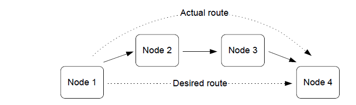
‘Many-to-one’ routing
A common scenario in a wireless network is the need for most network nodes to communicate with a single node that performs some centralized function, for example, a gateway. This node is often referred to as a concentrator.
In order to establish communication with the concentrator, each remote node may initiate a ‘route discovery’, resulting in a corresponding entry in the Routing table of each routing node along the way. If most network nodes need to communicate with the concentrator, many such route discoveries may be initiated. Where the resulting routes have a common leg, the relevant Routing table entries will not be duplicated but shared. However, a large number of simultaneous route discoveries may require significant memory space in the nodes near the concentrator for the temporary storage of route discovery information, and possibly result in memory overflow and traffic congestion.
A more efficient method of establishing routes to a concentrator is for the concentrator to initiate a ‘many-to-one’ route discovery for routes from all other network nodes to itself. To do this, the concentrator broadcasts a route discovery request and the Routing tables are updated as the broadcast propagates through the network. Since no responses are generated, the temporary storage of route discovery information is not required and network traffic congestion is minimized.
Many-to-one route discovery is illustrated in the figure below.
‘Many to one’ routing

In order to avoid the storage of return routes (from the concentrator) in the Routing tables of intermediate nodes, the technique of source routing is used - the outward route taken by a message to the concentrator is remembered by the concentrator and embedded in the response message. In this case, the response message must carry up to 30 addresses of the nodes along the return route (maximum number of hops allowed is 30).
Parent topic:Network routing
Parent topic:ZigBee PRO architecture and operation
Network communications
This section considers the processes that are needed to allow a network of devices to exchange information and perform useful functions. In order to communicate with each other, two nodes must be compatible in that one node can produce data which the other node can accept and interpret in a meaningful way. For example, a temperature sensor node produces a temperature measurement that a heating controller node can use to control a central heating system.
When a new node joins a network, it must find compatible nodes with which it is able to communicate - this process is facilitated by the Service Discovery mechanism. It must then choose which of the compatible nodes it will communicate with. A method of pairing nodes for easy communication is provided by the binding mechanism.
Note: While you should always use Service Discovery to find compatible nodes, binding is an optional method for pairing compatible nodes.
Service Discovery and binding are covered in the sub-sections below.
Service discovery
A device joining a network must be able to find other devices in the network that can use the information it provides, or that can generate the information needed by the device to perform its own function. A node can use Service Discovery to find nodes with which it can communicate. Service Discovery is introduced in Section 3.4.6.
The node requests the required services from other nodes by means of a broadcast message that propagates throughout the network. Any node that has the requested services then unicasts a response back to the requesting node. This means that the requesting node may receive more than one response.
A response includes the network address of the remote node that contains the requested services. The node stores this address locally and the application can then use the address for all future communications to the remote node. This is referred to as direct addressing.
Alternatively, rather than using direct addressing in their communications, two nodes can communicate through the binding mechanism, described in Section 3.6.2 below.
Parent topic:Network communications
Binding
Once two nodes have been found to be compatible through Service Discovery (see Section 3.6.1), they may be paired for communication purposes. For example, a light- switch may be paired with a particular light, and we must ensure that this light-switch only ever switches the light that it is intended to control. An easy way to pair nodes for communication is provided by the binding mechanism.
Binding allows nodes to be paired in such a way that a certain type of output data from one node is automatically routed to the paired node, without the need to specify the destination address and endpoint every time. The two nodes must first be bound together using the address and relevant endpoint number for each node - these can be obtained through Service Discovery, described in Section 3.6.1. A binding has a source node and a destination node, relating to the direction in which data is sent between the nodes (from source to destination). The details of a binding are stored as an entry in a binding table, normally held on the source node of the binding or sometimes on another nominated node.
In order to establish a binding, it must be requested in either of the following ways:
Binding request is submitted to the source node for the binding by either the source node itself or a remote node (not one of the nodes to be bound).
Binding requests are submitted to the Coordinator by the source and destination nodes for the binding (for example, by pressing a button on each node to generate a binding request). The two binding requests must be received within a certain timeout period.
During the binding process, the Binding table for the source node is updated or, if necessary, created.
Binding occurs at the application level using clusters (described in Section 3.4.5). In order for two applications to be bound, they must support the same cluster.
The binding between two applications is specified by:
The node address and endpoint number of the source of the binding (for example, a light-switch).
The node address and endpoint number of the destination of the binding (for example, the load controller for a light).
The cluster ID for the binding.
The following types of binding can be achieved:
One-to-one: This is a simple binding in which an endpoint is bound to one (and only one) other endpoint, requiring a single Binding table entry.
One-to-many: This is a binding in which a source endpoint is bound to more than one destination endpoint. The binding is achieved by having multiple Binding table entries for the same source endpoint.
Many-to-one: This is a binding in which more than one source endpoint is bound to a single destination endpoint. The binding is achieved by multiple nodes having one-to-one bindings for the same destination endpoint.
These are illustrated in the figure below.
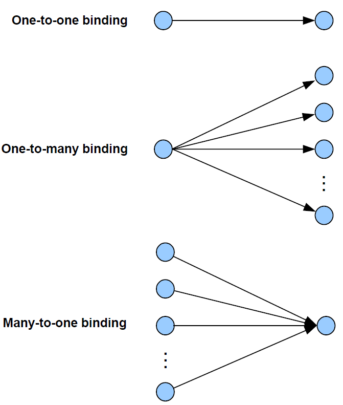
As an example of these bindings, consider a switch and load controller for lighting:
In the one-to-one case, a single switch controls a single light
In the one-to-many case, a single switch controls several lights
In the many-to-one case, several switches control a single light, such as a light on a staircase, where there are switches at the top and bottom of the stairs, either of which can be used to switch on the light
It is also possible to envisage many-to-many bindings where in the last scenario there are several lights on the staircase, all of which are controlled by either switch.
The way bindings are configured depends on the type of network (described in Section2.6), as follows:
Pre-configured system: Bindings are factory-configured and stored in the application image.
Self-configuring system: Bindings are automatically created during network installation using discovery software that finds compatible nodes/clusters.
Custom system: Bindings are created manually by the system integrator or installation technician, who may use a graphical software tool to draw binding lines between clusters on nodes.
Parent topic:Network communications
Parent topic:ZigBee PRO architecture and operation
Detailed architecture
This section elaborates on the simplified software architecture presented in “Section 3.1”. The detailed architecture is illustrated in the figure below.
Detailed software architecture
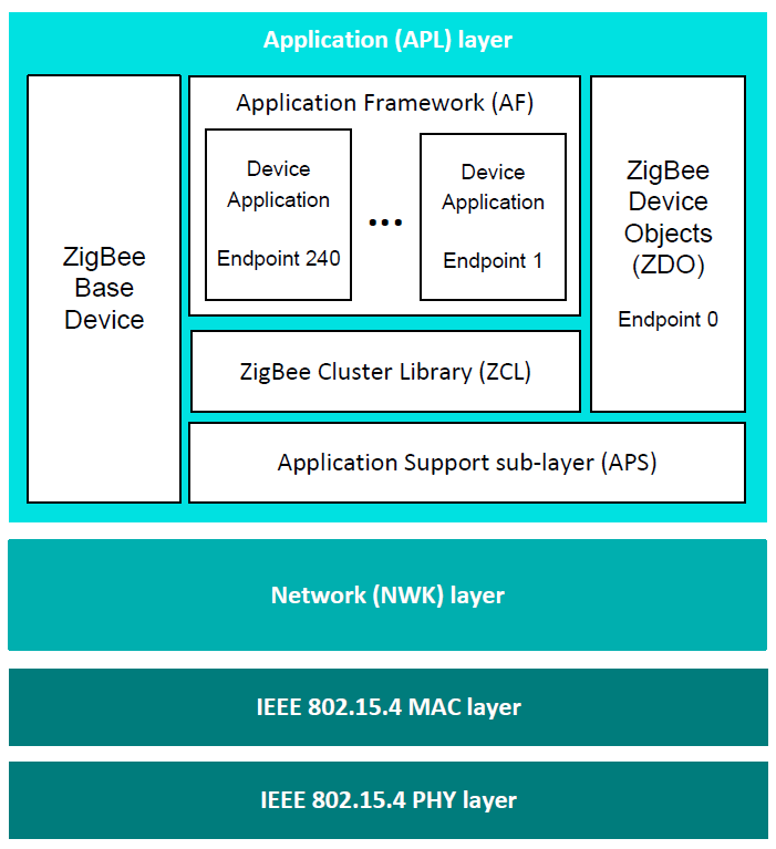
Software levels
The preceding figure Figure shows the architecture diagram (from top to bottom).
Application (APL) Layer
This includes:
Applications: Up to 240 application instances can be supported on a single ZigBee node. Each application instance communicates via an endpoint, where endpoints are numbered between 1 and 240 (note that endpoint 0 is reserved for the ZDO of the node - see below).
Application Framework (AF): The AF facilitates interaction between the applications and the APS layer (see below) through an interface known as a Service Access Point or SAP.
ZigBee Device Objects (ZDO): The ZDO represents the ZigBee node type of the device (Coordinator, Router, or End Device) and has a number of communication roles. The ZDO communicates via endpoint 0. For more information, refer to “Section 3.4.7”.
ZigBee Base Device: This device is required for all ZigBee 3.0 nodes and deals with essential tasks for the whole node, such as commissioning. It does not occupy an endpoint.
ZigBee Cluster Library (ZCL): The ZCL provides the standard ZigBee clusters used by the device applications that run on the endpoints.
Application Support sub-layer (APS): The APS layer is responsible for:
Communicating with the relevant application - for example, when a message arrives to illuminate an LED, the APS layer relays this instruction to the responsible application using the endpoint information in the message.
Maintaining binding tables (see “Section 3.6.2”) and sending messages between bound nodes.
Providing communication with the Trust Centre to obtain authorization.
The APS layer has an associated database, called the APS Information Base (AIB). This contains attributes that mainly relate to system security.
Parent topic:Software levels
Network (NWK) layer
The NWK layer handles network addressing and routing by invoking actions in the MAC layer. It provides services for:
Starting the network
Assigning network addresses
Adding devices to and removing them from the network
Routing messages to their intended destinations
Applying security to outgoing messages
Implementing route discovery and storing Routing table information
The NWK layer has an associated database, called the NWK Information Base (NIB). This contains attributes required in the management of the NWK layer.
Parent topic:Software levels
Physical/Data link layers
This consists of the IEEE 802.15.4 PHY and MAC layers, described in Section 3.1,”Architectural overview”.
Note: The Security Service Provider (not shown in the figure) spans the APS and NWK layers, providing security services - for example, security key management, datastream encryption and decryption. It may use hardware functions provided in the node to perform the encode and decode operations efficiently.
Parent topic:Software levels
Parent topic:Detailed architecture
Parent topic:ZigBee PRO architecture and operation