Build the USB examples in MCUXpresso SDK
This section describes how to compile the USB stack and examples, download a binary image, and run the examples.
Requirements for building USB examples
The TWR-K22F120M Tower System module or FRDM-K64F Freedom platform is used as an example in this document. The process for compiling, downloading, and running examples is similar on all other boards. For a detailed version of the toolchain software, see the MCUXpresso SDK Release Notes (document MCUXSDKRN).
Hardware
TWR-K22F120M Tower System module and (optional) TWR-SER Tower System module and Elevator
MCUXpresso SDK Boards
J-Link debugger (optional)
USB cables
Parent topic:Requirements for building USB examples
Software
MCUXpresso SDK release package
IAR Embedded Workbench for Arm Version 8.11.3
Keil µVision5 Integrated Development Environment Version 5.23 , available for Arm Cortex-M4 devices
MCUXpresso IDE v10.1.0
Makefiles support with GCC revision 6-2017-q2-update from Arm Embedded
Parent topic:Requirements for building USB examples
Parent topic:Build the USB examples in MCUXpresso SDK
USB code structure
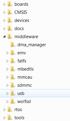
The USB code is located in the folder:
<install_dir>/middleware/usb
|
|
The USB folder includes the source code for stack and examples. Note that the version number of the USB folder may vary.
|
|
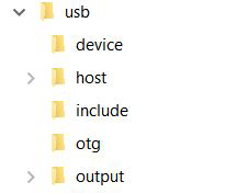
The USB folder includes the following subfolders:
device
This subfolder includes the device controller driver and common device driver for the USB device.
host
This subfolder includes the host controller driver and common host driver for the USB host.
include
This subfolder includes the definitions and structures for the USB stack.
otg
This subfolder includes the OTG controller driver, common OTG driver and OTG peripheral driver for the USB OTG.
output
This subfolder includes the files that are specially used by the New Project wizard.
Note: For different USB stack versions, the folder structure may be a little different. See the folder structure in the release package to get the exact folder structure.
Parent topic:Build the USB examples in MCUXpresso SDK
Compiling or running the USB stack and examples
Note: The USB example may not support all compilers. The steps below describes how to compile and run on all compilers. Check the specific MCUXpresso SDK documentation to know about the supported compilers for the USB example.
Step-by-step guide for MCUXpresso IDE
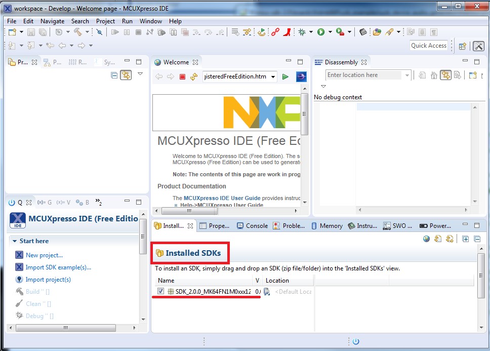
Prepare a compressed release package, such as SDK_2.0_FRDM-K64F.zip.
Open MCUXpresso IDE and drag and drop the MCUXpresso SDK (zip file/folder) into the “Installed SDKs”. The MCUXpresso SDK should install.
|
|
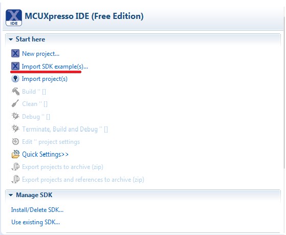
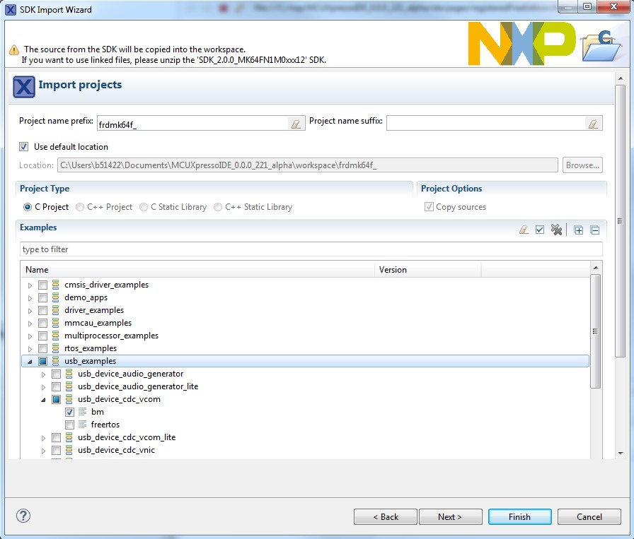
To select an example, select the “Import SDK example(s)” button. Click the “Next” button after selecting the available board.
|
|
|
|
To import one example, click the “Finish” button after selecting the available example.
|
|
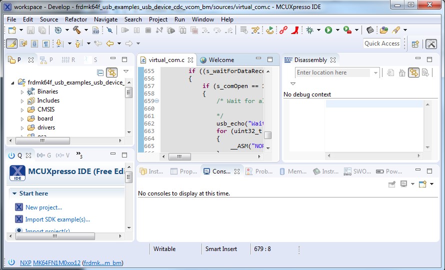
After importing, the window should look like the below figure.
|
|
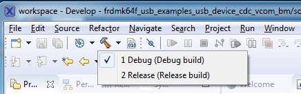
Choose the appropriate build target, “Debug” or “Release”, by left-clicking the build configuration icon as show in the below figure.
|
|
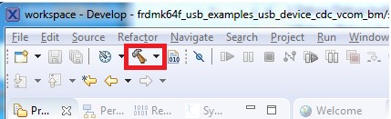
If the project build does not begin after selecting the desired target, left-click the build icon to start the build.
|
|
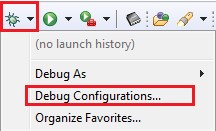
To check debugger configurations, click the down arrow next to the green debug button and select “Debug Configurations”.
|
|
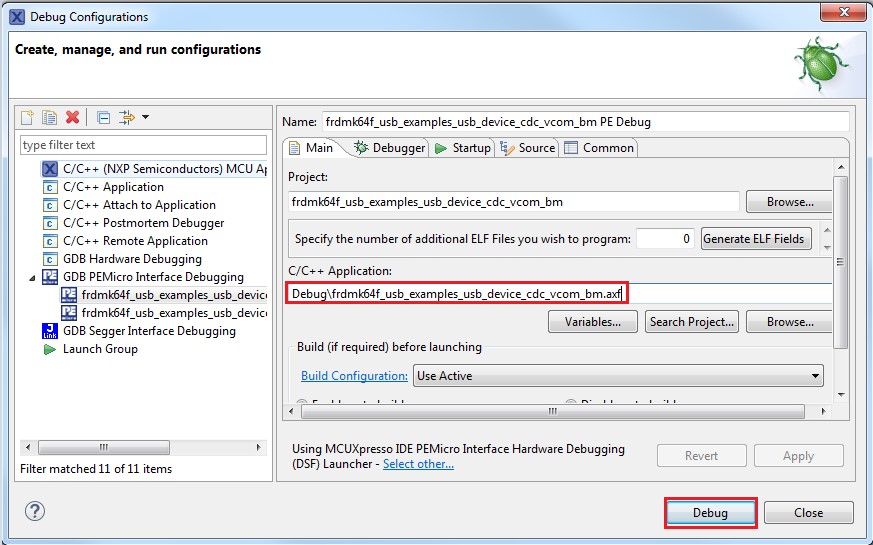
After verifying the debugger configurations are correct, click the “Debug” button.
|
|
The application is downloaded to the target and automatically runs to main():
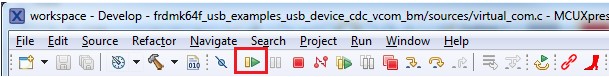
Run the code by clicking the “Resume” button to start the application:
|
|
See the example-specific document for more test information.
Parent topic:Compiling or running the USB stack and examples
Step-by-step guide for IAR
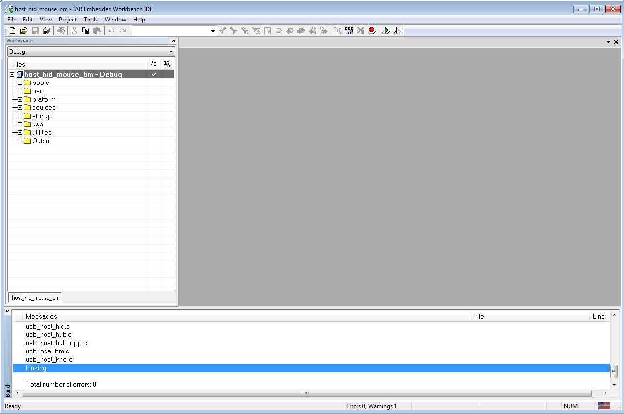
This section shows how to use IAR. Open IAR as shown in this figure:
Open the worksace corresponding to different examples.
For example, the workspace file is located at: <install_dir>/boards/twrk22f120m/usb_examples/usb_host_hid_mouse/bm/iar/host_hid_mouse_bm.eww.
|
|
Build the host_hid_mouse_bm example.
Connect the micro USB cable from a PC to the J25 of the TWR-K22F120M Tower System module to power on the board.
Click the “Download and Debug” button. Wait for the download to complete.
Click the “Go” button to run the example.
See the example-specific readme.pdf for more test information.
Parent topic:Compiling or running the USB stack and examples
Step-by-step guide for Keil µVision5
This section shows how to use Keil µVision5. Open Keil µVision5 as shown in this figure:
Open the workspace corresponding to different examples.
For example, the workspace file is located in <install_dir>/boards/twrk22f120m/usb_examples/usb_host_hid_mouse/bm/mdk/host_hid_mouse_bm.uvmpw.
|
|
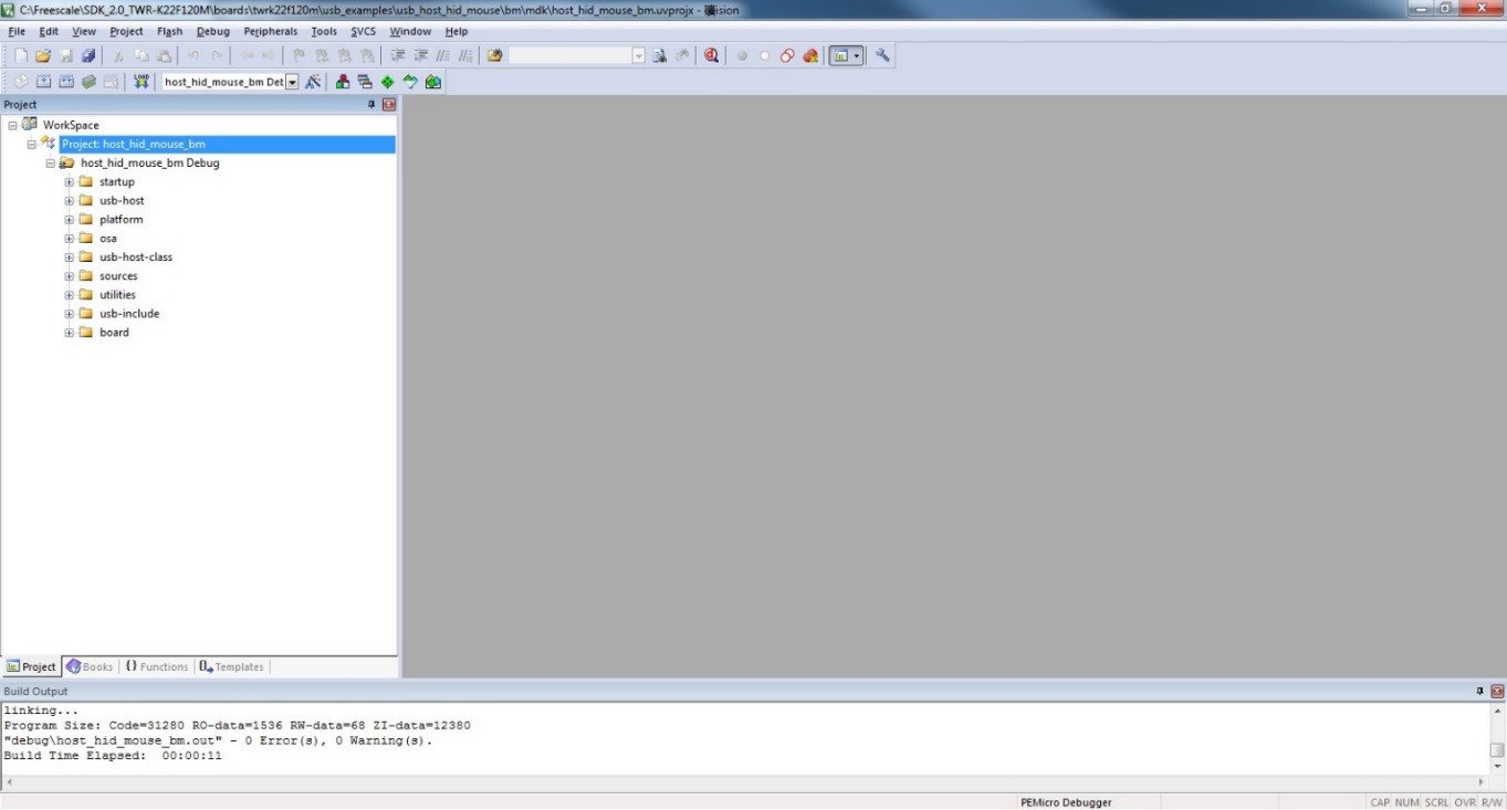
Build the host_hid_mouse_bm example.
Click the “Start/Stop” debug session button. Wait for the download to complete.
Click the “Go” button to run the example.
See the example-specific readme.pdf for more test information.
Parent topic:Compiling or running the USB stack and examples
Step-by-step guide for ARMGCC
Setup tool chains
Parent topic:Step-by-step guide for ARMGCC
Install GCC Arm embedded tool chain
Download and install the installer from www.launchpad.net/gcc-arm-embedded.
Parent topic:Step-by-step guide for ARMGCC
Install MinGW
Download the latest mingw-get-setup.exe.
Install the GCC Arm Embedded toolchain. The recommended path is C:/MINGW.
Note: The installation path should not contain a space.
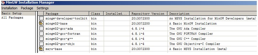
Ensure that the mingw32-base and msys-base are selected under basic setup.
Click “Installation” and “Apply changes”.
|
|
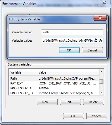
Add paths C:/MINGW/msys/1.0/bin;C:/MINGW/bin to the system environment. If the GCC Arm Embedded tool chain was not installed at the recommended location, the system paths added should reflect this change else the tool chain will not work. An example using the recommended installation locations is shown below.
|
|
Parent topic:Step-by-step guide for ARMGCC
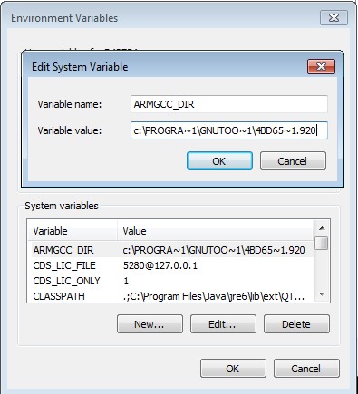
Add new system environment variable ARMGCC_DIR
Create a new system environment variable ARMGCC_DIR. The value of this variable should be the short name of the Arm GCC Embedded tool chain installation path.
|
|
Parent topic:Step-by-step guide for ARMGCC
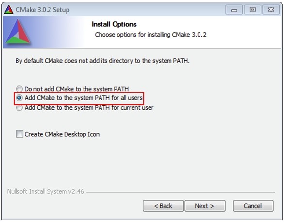
Install CMake
Download CMake 3.0.1 from www.cmake.org/cmake/resources/software.html.
Install CMake 3.0.1 and ensure that the option “Add CMake to system PATH” is selected.
|
|
Parent topic:Step-by-step guide for ARMGCC
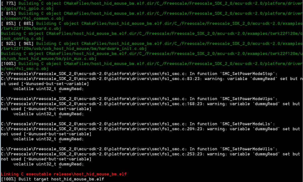
Build the USB demo
Change the directory to the project directory:<install_dir>/boards/twrk22f120m/usb_examples/usb_host_hid_mouse/bm/armgcc.
Run the build_all.bat. The build output is shown in this figure:
|
|
Parent topic:Step-by-step guide for ARMGCC
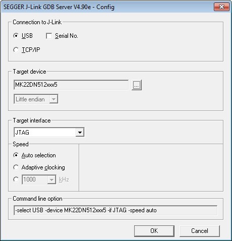
Run a demo application
This section describes steps to run a demo application using J-Link GDB Server application.
Connect the J-Link debug port to the SWD/JTAG connector of the board.
Open the J-Link GDB Server application and modify your connection settings as shown in this figure.
|
|
**Note:** The target device selection should be MK22FN512xxx12. The target interface should be SWD.
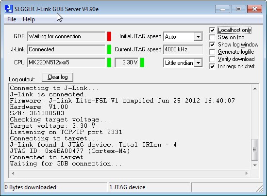
After the connection is estabilished, the screen would resemble the figure below:
|
|
**Note:** The CPU selection should be CPU to: MK22FN512xxx12.
Open the Arm GCC command prompt and change the directory to the output directory of the desired demo. For this example, the directory is:
<install_dir>/boards/twrk22f120m/usb_examples/usb_host_hid_mouse/bm/armgcc/debug.
Run the command “arm-none-eabi-gdb.exe <DEMO_NAME>.elf”. Run these commands:
“target remote localhost: 2331”
“monitor reset”
“monitor halt”
“load”
“monitor reset”
The application is downloaded and connected. Execute the “monitor go” command to start the demo application.
See the example-specific document for more test information.
Parent topic:Step-by-step guide for ARMGCC
Parent topic:Compiling or running the USB stack and examples
Parent topic:Build the USB examples in MCUXpresso SDK
USB stack configuration
Device configuration
A device configuration file is set up for each example, such as:
<install_dir>/boards/twrk22f120m/usb_examples/usb_device_hid_mouse/bm/usb_device_config.h
This file is used to either enable or disable the USB class driver and to configure the interface type (high-speed or full speed). The object number is configurable either to decrease the memory usage or to meet specific requirements.
If the device stack configuration is changed, rebuild the example projects. For each device, follow these steps.
If the board is a Tower or Freedom platform, enable the following macros:
Enable #define USB_DEVICE_CONFIG_KHCI (0U) macro for full speed.
Enable #define USB_DEVICE_CONFIG_EHCI (0U) macro if the board supports high-speed.
Note: Only EHCI support pin detect feature.
If board is part of the LPC series, enable the following macros:
Enable #define USB_DEVICE_CONFIG_LPCIP3511FS (0U) macro for full speed.
Enable #define USB_DEVICE_CONFIG_LPCIP3511HS (0U) macro if the board supports high-speed.
Parent topic:USB stack configuration
Host configuration
A host configuration file is set up for each example, such as:
<install_dir>/boards/twrk22f120m/usb_examples/usb_host_hid_mouse/bm/usb_host_config.h
This file is used to either enable or disable the USB class driver. The object number is configurable either to decrease the memory usage or to meet specific requirements.
If the Host stack configuration is changed, rebuild the example projects.
For each Host, follow these steps.
If the board is a Tower for Freedom platform, enable the following macros:
Enable this macro for full speed.
#define USB_HOST_CONFIG_KHCI (0U)
Enable this macro if the board supports high-speed.
#define USB_HOST_CONFIG_EHCI (0U)
Note: Only EHCI support pin detect feature.
If board is part of the LPC series, enable the following macros:
Enable this macro for full speed.
#define USB_HOST_CONFIG_OHCI (0U)
Enable this macro if the board supports high-speed.
#define USB_HOST_CONFIG_IP3516HS (0U)
Parent topic:USB stack configuration