Overview
This Quick Start Guide provides a step-by-step overview to help you install, configure, and begin using the System Manager (SM) Configuration tool efficiently. Whether you are new to Config Tools for i.MX Applications Processors or looking to the System Manager (SM) Configuration tool into your production process, this guide will help you get started quickly.
The System Manager (SM) is an application that runs on a Cortex-M processor on many NXP i.MX processors. The Cortex-M is the boot core, runs the boot ROM which loads the SM (and other boot code), and then branches to the SM. The SM then configures some aspects of the hardware such as isolation mechanisms and then starts other cores in the system. After starting these cores, it enters a service mode where it provides access to clocking, power, sensor, and pin control via a client RPC API based on ARM’s System Control and Management Interface (SCMI). To facilitate isolation between cores, the SM partitions the SoC into logical machines (LM) which have statically configurable access rights to both hardware and RPC API calls.
Hardware requirements
Detailed requirements to start the System Manager Configuration tool are listed in the User Guide for Config Tools for i.MX (Desktop) (document IMXUG).
Software requirements
The System Manager Configuration tool is a part of Config Tools for i.MX Applications Processors that can be executed on Windows, Linux, or MacOS. The detailed requirements are listed in the Config Tools for i.MX Release Notes (document MCUXCTIMXRN).
Installing and configuring the System Manager Configuration tool
The System Manager Configuration tool is a part of the Config Tools for i.MX. This software is available as an online version (using a web browser) and also as a desktop application installed on the host machine. For the desktop setup executable, there is an installer available at https://nxp.com. For Windows and MacOS, the installers work as a wizard that guides you step by step through the installation process. The Debian package is available for Linux. The details about the installation can be found in the Installation Guide for Config Tools for i.MX (document IMXIUG).
To get started with the System Manager Configuration tool on an NXP board, download the GitHub repository and compile the SM for the target configuration.
Using the tool
Open the System Manager (SM) Configuration tool.
Open the Project Configuration wizard by pressing Project Settings button.
Set the configuration name.
Set the SM project location path (for example, downloaded from the GitHub repository ).
To create a new empty configuration, select a board supported by SM FW and click the Create a new configuration button (this option is suitable for developers of new or unsupported boards).
To import the existing board configuration, choose between the CFG and JSON file and click the corresponding button, then set the path with the file to be imported.
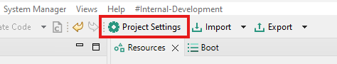
Project Settings button
Note: Problems that occur during the configuration import are displayed in the report dialog that can be exported. If there are issues, review the report and adjust the configuration accordingly.
System and Details View
For navigation through the general system configuration, use the System View that shows tree nodes settings. These are the main categories that can be configured.
Project Configuration – SM project configuration name and description, compiler Mak file configuration
Board Configuration – Board specific settings, SM debug options, Global Assignment Templates definition, creation of custom User Macro Resources
Logical Machines – LM specific settings (for example, RPC), Mode Select Configurations from LM’s perspective, Start-Stop Sequences configuration, Assignment Templates definition
Agents – SCMI Agent specific settings (for example, Mailbox), Assignment Templates definition
RPC Channels – Channel settings (for example, transport)
Domains – DOM specific settings, Assignment Templates definition
mSel Configurations Overview - Mode Select Configurations from mSel’s perspective
To configure a generic System Manager project setting, for example, Project Mak file or debug features, use the System View’s tree to select the desired node. Every selection of the tree node shows available configuration settings in the configuration Details View. Using the Expand/Collapse buttons on the System View’s header you can expand/collapse all child nodes of the active selection.
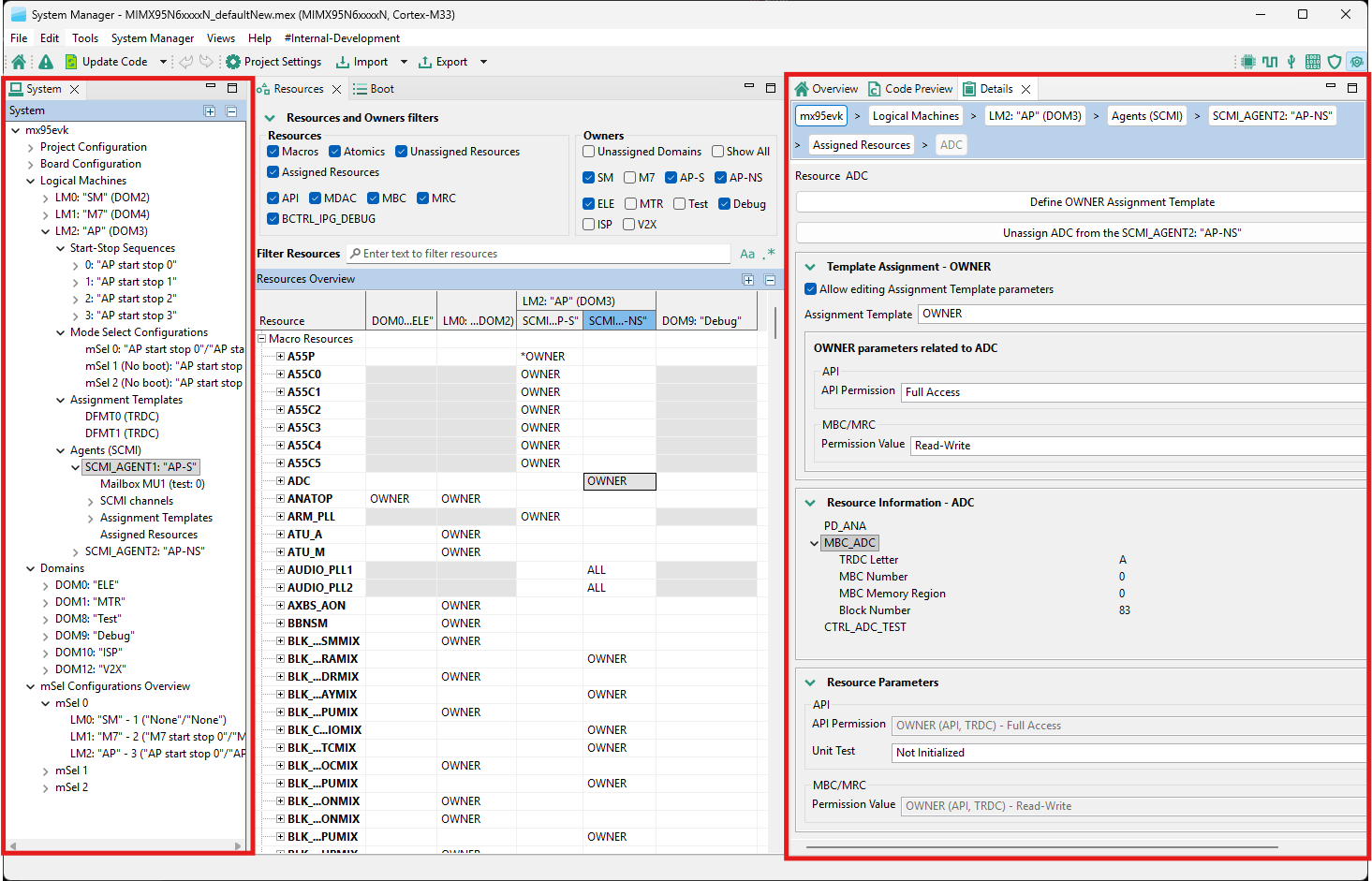
Configuring a selected element in System View (left) using the Details View (right)
Resources View
To assign a resource to a Resource Owner (LM, SCMI_AGENT, DOM), use the Resources View. Note: Every Resource Owner is related to a specific RDC domain (DOM).
Assign and configure Resource Parameters - Select the cell with the corresponding Resource (row) and the Resource Owner (column) in the Resources View. Then click the Assign button in the configuration Details view.
Assign a resource with pre-configured Assignment Templates. To do this, configure the Assignment Templates for your desired Resource owner using the System and Details Views and set the name (identifier) and Resource parameters that will be configured (parameters that do not relate to the assigning Resource are ignored). Note: Resource cells that cannot be assigned to a specific owner are greyed out.
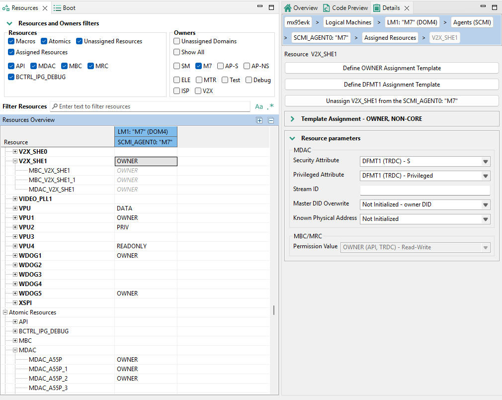
Example of Resource assignment - V2X_SHE1 to Agent M7 using OWNER and automatic DFMT1 Assignment Template
Create a new memory sector - Select the corresponding Resource (row) with the <MEM> suffix and the Resource Owner (column) in the Resources View. Double-click the desired cell and select Create a new memory sector. Then configure the memory sector parameters (Start Address, Size or End Address, and Permissions) in the Details View.
Assign an existing memory sector to a Resource owner - Expand the Resource (row) with the <MEM> suffix node, select the memory sector, and double-click the cell to select the template or assign the memory sector.
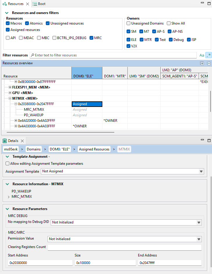
Example of Memory resource assignment - M7MIX<0x20380000-0x2047ffff> to ELE Domain
To modify parameters of the resource assignment, select the resource and use the Details View:
Use the Template Assignment section to select and see the configured parameters assigned by the Assignment Template. It is possible to directly modify the Assignment Template parameters by setting a checkbox to enable editing. Note: updating the selected Assignment Template affects all Resources that are assigned to this template.
To configure additional parameters to the selected Assignment template, select the settings below the Assignment Template selection. The parameters that are not available are not related to the Resource. The parameters that are grayed are configured by the Assignment Template and cannot be overwritten. To change the grayed setting value you have to create new, choose another or update the selected Assignment Template.
To remove Resource assignment, select the cell with the corresponding Resource (row) and the Resource Owner (column) in the Resources View. Then click the Unassign button in the configuration Details view.
To find a desired Resource or to adjust the overview table, use the Filter or Search bar. To achieve that, combine selection of Resources and Owners filters with the search bar filtering. The search bar is case-sensitive and supports regular expression search, it can be enabled by clicking the buttons on the right side of the search bar. Note: To see all Atomic Resources that are included in the resource assignment, expand Macro Resources in the Resources View.
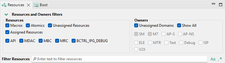
Filters and Search bar
Boot View
To configure a setting related to booting of the Logical Machines, use the Boot view.
To add or remove the mSel configuration, click the Add/Remove buttons in the header of the mSel Settings in the Boot View.
The mSel Section lists all available LMs
The boot order can be changed by Arrow buttons in the left side. When the Boot parameter is enabled, the index of the Logical Machine corresponds to the actual boot order (index 0 means that LM will not boot).
Configuration of the Skip flag suppresses an error invocation in case no image is available in the boot container.
Start and Stop Sequence of the LM is selected in the dropdown. To add, remove or modify a Start-Stop Sequence, select the LM to be affected from the desired mSel section and use the Details View.
Use plus/minus buttons to add or remove a Start-Stop Sequence
Double-click Start-Stop Sequence to open its configuration details to be modified
Modify the index (identifier) and user name of the Start-Stop Sequence
Use plus/minus buttons to add or remove a Resources Commands to be called in the sequence
Double click Resource Command to open its configuration details to be modified (selection of Resource Command, optional arguments, and unit test flag)
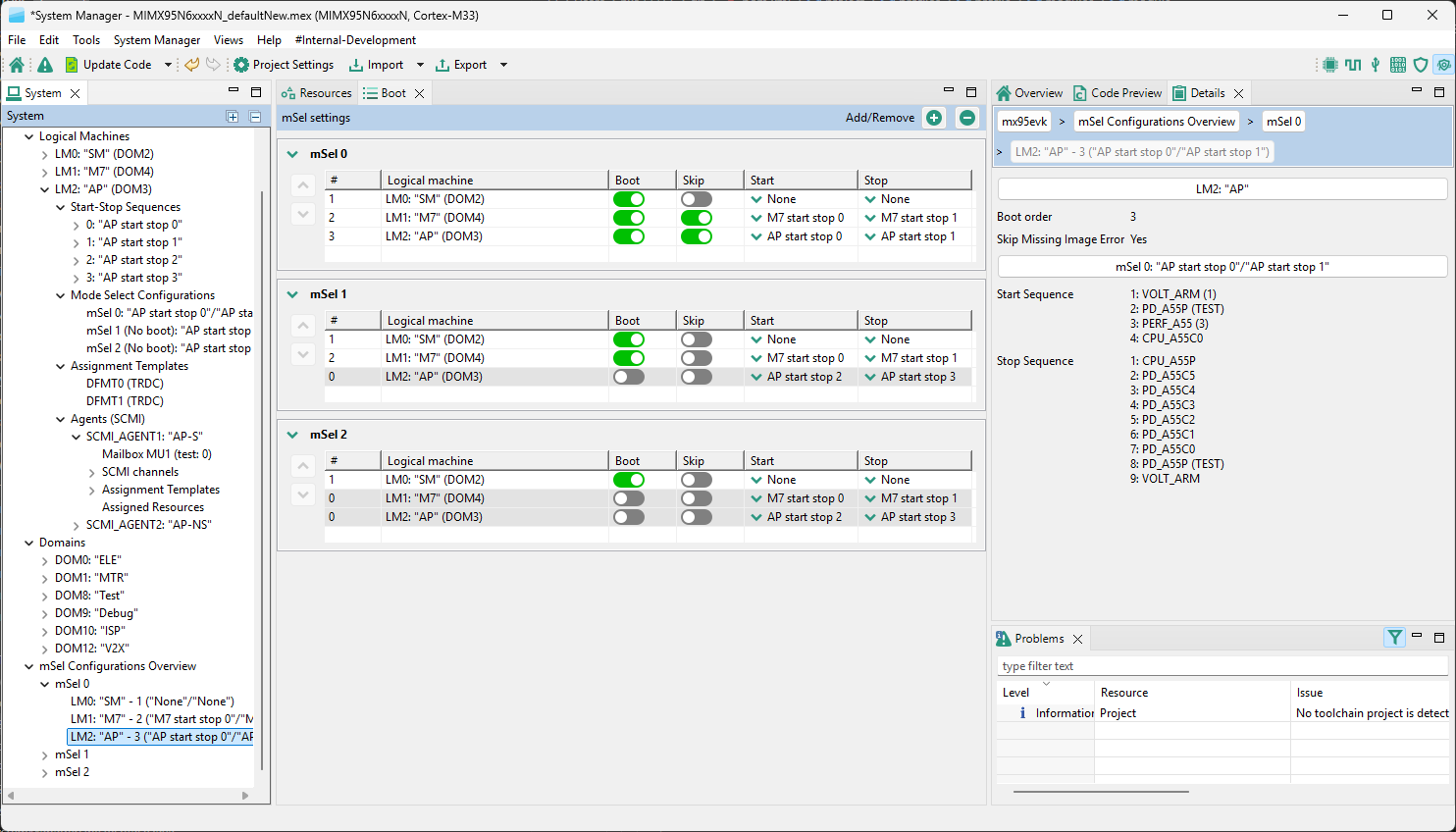
Boot View
References
User Guide for Config Tools for i.MX (Desktop) (document IMXUG)
Installation Guide for Config Tools for i.MX (document IMXIUG)
Config Tools for i.MX Release Notes (document MCUXCTIMXRN)
NXP System Manager Reference Manual (document SMRM)
Revision history
Document ID |
Release date |
Description |
|---|---|---|
UG10266 v.3.0 |
25 March 2026 |
Updated for v.26.03 |
UG10266 v.2.0 |
16 December 2025 |
Updated for v25.12 |
UG10266 v.1.0 |
18 September 2025 |
Initial version. |