PLU Configuration Tool#
The PLU Tool is an extension of the Peripheral Tool and configures the register initialization configuration component from the Peripheral Tool. The purpose of this tool is to configure the PLU peripheral using a user-friendly graphical approach instead of the long and difficult to visualize process of connecting the LUTs manually in the register initialization component.
Modes#
PLU Tool supports all modes from the PLU register initialization component.
Direct#
Direct mode configures the LUTs as they are mapped and connected in the tool. No optimizations are performed.
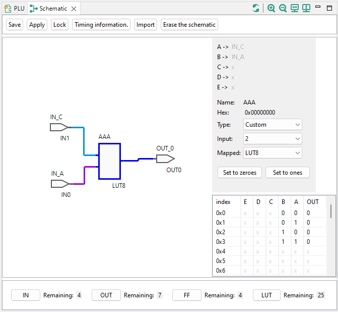
GUI overview in direct mode#
Logic gates#
Logic gates (Schematic) mode offers users the capability to optimize the schematic to use only some of the LUTs in the peripheral, effectively allowing more logic gates than there are LUTs available in the peripheral.

GUI overview in logic gates mode#
Verilog#
The tool can synthesize and optimize the model created by Verilog. Both Verilog modes take a given Verilog file/text, run the synthesis and optimization processes, and ask users to provide a mapping of some elements used in the Verilog (IN, OUT). Users can either select file with Verilog or write Verilog code in the textbox inside the component.
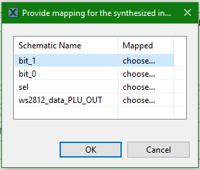
Mapping dialog of signals used in given Verilog code#
Mapping information in Verilog code#
The PLU Tool supports mapping specified in Verilog code for easier usage of the tool. This feature enables the capability to regenerate the PLU configuration from command-line application and provides default values for mapping in the GUI.
Block/code:
/**
 * ---Config tools mapping header---
 * symbol : pluSignal
 * r : IN3
 * s : IN5
 * q : OUT3
 * q_ : OUT7
 */
Workflow of Direct and Logic gates modes#
Direct mode#
In Direct mode, IN, OUT, LUT, and FF symbols can be added. IN and OUT symbols are selected from the PLU component instance and more can be added through the selection dialog. LUT symbols must have a name specified when created and have the custom type selected by default. They can be either changed to a different predefined type or the truth table can be modified by clicking the output value.
Logic gates#
In Logic gates mode, IN, OUT and FF symbols can be added the same way as in Direct mode. LUT symbols are not supported, logic gate symbols must be added instead. The final LUT count and their configuration will be determined by optimizing the schematic later.
Inputs and outputs dialog#
Dialog offers users unused inputs and outputs defined in the component. Users can create new inputs and outputs by opening a dialog to create them.
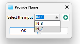
Selection of existing input#
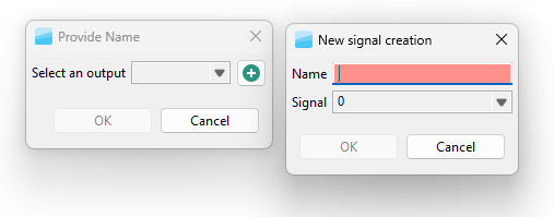
Creation of new input#
Creating LUT in schematic#
When the PLU is being configured in Direct mode, only a common LUT symbol can be added. In this mode, the name of the LUT must be provided during creation.
When PLU is being configured in Logic gates mode, only a logic gate can be added to the schematic. In this mode, the name is automatically created from the logic gate type and first available number (for example, AND3)
In both modes the name and number of connections can be changed after the LUT symbol or Logic gate symbol is created. The change can be performed by either double-clicking the symbol in schematic or by selecting it by clicking it. Then the details are displayed on right side of the Schematic view.

Editing of logic gate symbol#
Connecting elements in schematic#
Users can either start the connection by left click the output pin or right-click the body of the element to switch to connection mode. In connection mode, the future connection is drawn as a line from the output pin of the element to the position of a mouse. The input pins of elements are also highlighted by green circles. When users click the green circle by the left mouse button the connection is created.
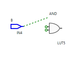
Connection mode#