User interface#
This chapter provides a detailed description of the user interface.
Start Development wizard#
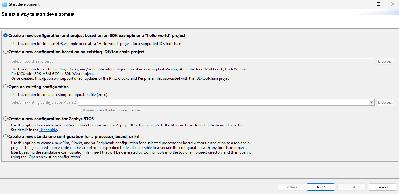
Upon starting MCUXpresso Config Tools, you are automatically welcomed by a startup wizard. With this wizard, you can create a configuration or open an existing one.
Note: To skip the wizard on subsequent startups, select the Always open last configuration checkbox below the Open an existing configuration option. You can also perform the same action by selecting the Automatically open previously used configuration checkbox in Preferences.
Start development wizard#
Note: The content of this wizard is similar to the wizard that you open by selecting File > New in the Menu bar.
Creating, saving, and opening a configuration#
In this context, configuration stands for common tools settings stored in an MEX (Microcontrollers Export Configuration)file. This file contains the settings of all available tools and can be used in both web and desktop versions.
The folder with the saved MEX file must contain exactly one project file to be able to parse the toolchain project. The file type depends on the toolchain of the project and can be one of the following:
Table Supported toolchain project files#
Toolchain |
Project file |
|---|---|
MCUXpresso for VS Code/SDK West |
project_info.json |
IAR Embedded Workbench |
EWP |
Keil MDK uVision |
UVPROJX |
Arm GCC |
CMakeLists.txt |
CodeWarrior with SDK |
.cproject |
Open-CMSIS csolution |
*.cbuild-gen-idx.yml |
See also MCUXpresso SDK Distribution Formats.
Creating a new configuration#
You can create a configuration from the Start development wizard or by selecting File > New from the Menu bar.
There are several options for creating a new configuration:
Create a new configuration and project based on SDK example - Use this option to clone an SDK example or create a “Hello world” project.
Create a new configuration based on existing toolchain project - Use this option to create configuration of an existing toolchain project.
Create a new configuration for Zephyr RTOS - Use this option to create a new configuration of pin muxing for Zephyr RTOS.
Create a new standalone configuration for a processor, board or kit - Use this option to create a new configuration for selected processor or board without association to a toolchain project.
If you start development for an NXP board or kit, we recommend starting by creating a configuration based on an MCUXpresso SDK example or by creating a new standalone configuration for a board or kit. Such configurations contain board-specific settings. If you select a new standalone configuration for a processor, the configuration will be empty.
After the new configuration is created, you can continue by importing an existing configuration from an MEX file. It is useful if you already have a configuration available or if you want to reuse a previous configuration. To import an existing configuration from an MEX file, select File > Import… > Import configuration (*.mex) from the Menu bar.
Cloning an SDK example#
You can create a configuration by cloning an SDK example project for IAR Embedded Workbench, Keil μVision, CodeWarrior Development Studio, and/or Arm GCC Embedded (command line). The resulting project contains all source files and libraries to build the project and can be easily customized, shared, or put under a control version system.
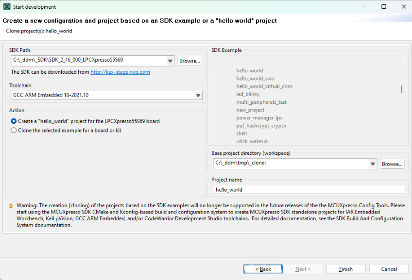
Note: The creation (cloning) of the projects based on the SDK examples will no longer be supported in the future releases of the MCUXpresso Config Tools. Instead, use the MCUXpresso SDK command line tools and west build system. For detailed documentation, see the MCUXpresso SDK Command Line Development documentation.
SDK example cloning is supported for MCUXpresso SDK 2.2 and higher.
Note: To be able to clone an SDK example or create a “hello_world” project, you must first download an SDK package. For more information about SDK packages offered by NXP Semiconductors, refer to the MCUXpresso Software Development Kit.
Note: If the server is unavailable, and device data is not cached, creating the project fails.
Cloning SDK#
To clone an SDK example, do the following:
In the Start development wizard, select Create a new configuration based on an SDK example or a “hello world” project. Alternatively, in the Menu bar, select File > New.
Click Next.
Specify the path to your locally saved SDK package.
Choose the toolchain that you want to create the project for.
Choose the SDK example that you want to clone.
Specify a base project directory to save your project to.
Specify the project name.
Click Finish.
You can also create a basic, minimally customized “hello_world” project without having to select an SDK example from the package. To create a “hello_world” project, do the following:
In the Start development wizard, select Create a new configuration based on an SDK example or a “hello world” project. Alternatively, in the Menu bar, select File > New.
Click Next.
Specify the path to your locally saved SDK package.
Choose the toolchain that you want to create the project for.
Select Create “hello_world”.
Specify a base project directory to save your project to.
Specify the project name.
Click Finish.
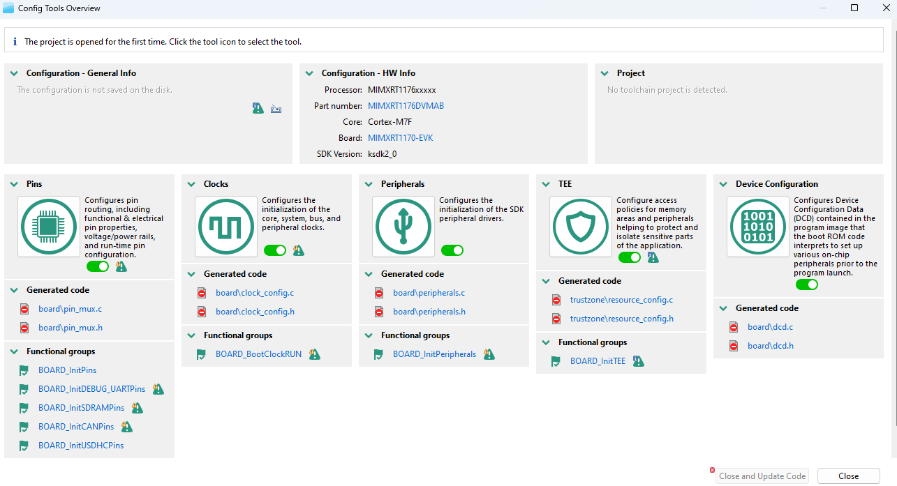
The Config Tools Overview window shows the details of the configuration and supported tools. Now, select a tool by clicking its icon.
Creating a new toolchain configuration#
You can create a configuration for an existing toolchain project. Once done, configuration files associated with the project are updated directly.
MCUXpresso Config Tools currently supports the following toolchains:
MCUXpresso for VS Code/SDK West
IAR Embedded Workbench
Keil MDK uVision
Arm GCC
CodeWarrior with SDK
Note: For proper functionality of Config Tools, it is required that the toolchain project originates from the SDK package downloaded from MCUXpresso SDK Builder, has been created using the cloning feature of Config Tools or has been created using MCUXpresso for VS Code and MCUXpresso SDK GitHub.
To create a configuration based on an existing IDE/Toolchain project, do the following:
In the Start development wizard, select the Create a new configuration based on an existing IDE/Toolchain project. Alternatively, in the Menu bar, select File > New.
Click Browse.
Select the project file and confirm by clicking OK.
Click Finish.
Creating a new configuration for SDK West#
For Arm GCC or MCUXpresso for VS Code toolchains, you can create a configuration for a new format of MCUXpresso SDK that uses the SDK West tool.
If you are using MCUXpresso for Visual Studio Code, you can open Config Tools from there via the context menu for the project. This also opens or creates a new configuration if it does not exist. See Working with MCUXpresso Config Tools for detailed guidelines. Otherwise, it is possible to handle the SDK project manually using the following steps:
Before using Config Tools, run the west command to get the project information for Config Tools from the SDK project files, for example:
west cfg_project_info -b lpcxpresso55s69 ...mcuxsdk/examples/demo_apps/hello_world/ -Dcore_id=cm33_core0
This results in the creation of the project information JSON file that is searched by the Config Tools when the configuration is created. The parameters of the command should match the build parameters that will be used for the project.
In the Start development wizard, select Create a new configuration based on the existing IDE/Toolchain project, and select the created “cfg_tools” subfolder as a project folder (for example: …
mcuxsdk/examples/demo_apps/hello_world/cfg_tools/).
Creating a new configuration for Zephyr RTOS#
You can create a configuration, that generates .dtsi file with pin control that is possible to include in the board device tree. There will be offered only processors/boards
After the configuration, move the generated file to the proper location in your Zephyr board, application folder, or repository. Consult Zephyr RTOS documentation for the appropriate placement and usage of the Pin Control file.
In the context of Zephyr RTOS, only the Pins tool is supported allowing pin routing and configuration.
You can create a configuration that generates a .dtsi file with pin control that can be included in the board device tree. Only processors and boards compatible with the Zephyr (https://www.nxp.com/zephyr) will be offered as the SDK version.
In the Start development wizard, select Create a new standalone configuration for Zephyr RTOS. Alternatively, in the Menu bar, select File > New.
Click Next.
Select the processor, board, or kit from the list. Note: When working offline, only locally stored options will be available. For further details, refer to the Working Offline section.
Name your configuration. Optionally, select the processor package, core, and SDK version.
Click Finish.
Using the generated files#
There are some additional manual steps needed to integrate the generated files:
After the configuration, write the files to disk using the Update Code command or via the Export command.
Move the generated device tree (
.dtsi) file to the proper location in your Zephyr board, application folder, or repository. If you have a custom hardware, it is a common practice to create a custom board in the Zephyr RTOS rather than modifying standard board files that are shared by many projects. Consult Zephyr RTOS documentation for details on how to work with pin control and the steps for creation of the custom board. Note: Alternatively, you can leverage the content of the.dtsifile to create a device tree overlay file for your application.In case features not supported by Zephyr RTOS are used, the Pins tool provides
pin_mux.c/hfiles. It is necessary to addpin_mux.c/hto yourcmakefile so they are part of the build and call the generated functions in your code.
Limitations#
The pin configuration and routing cannot be restored from the generated .dtsi file because there is no import functionality for this format. Keep the original .mex file for further regeneration of the file(s).
Creating a new standalone configuration#
You can create a configuration that is not part of any toolchain project.
You can later include this configuration in a project by saving the configuration (MEX) file in the toolchain project folder.
Creating a new configuration#
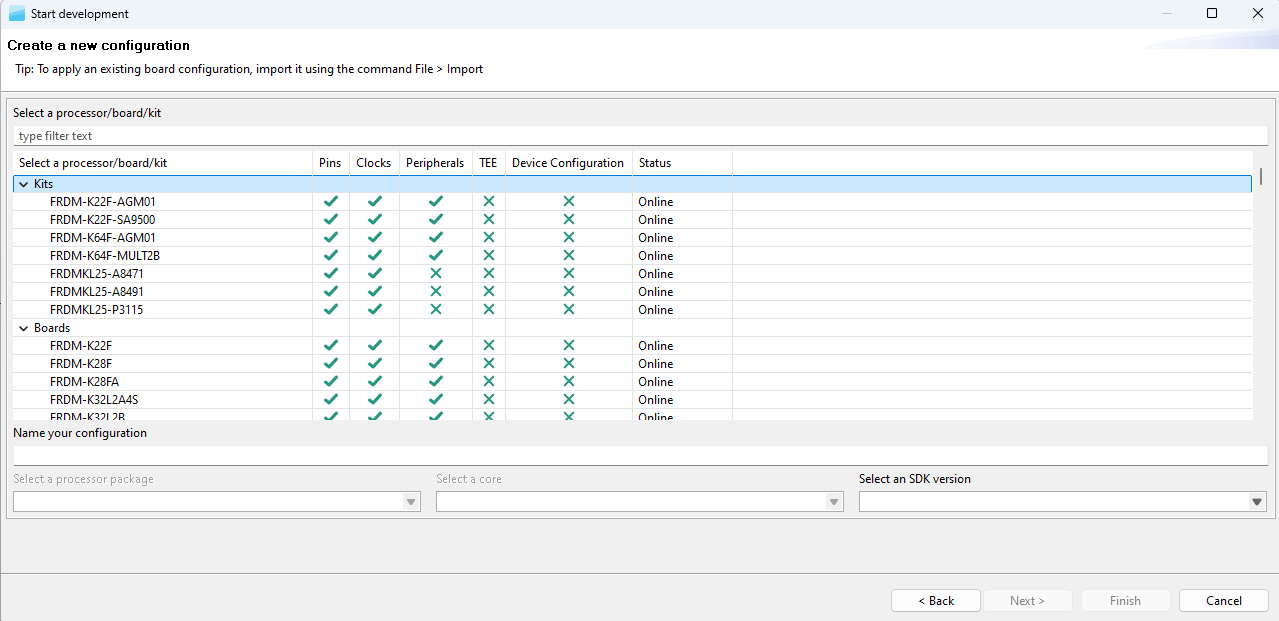
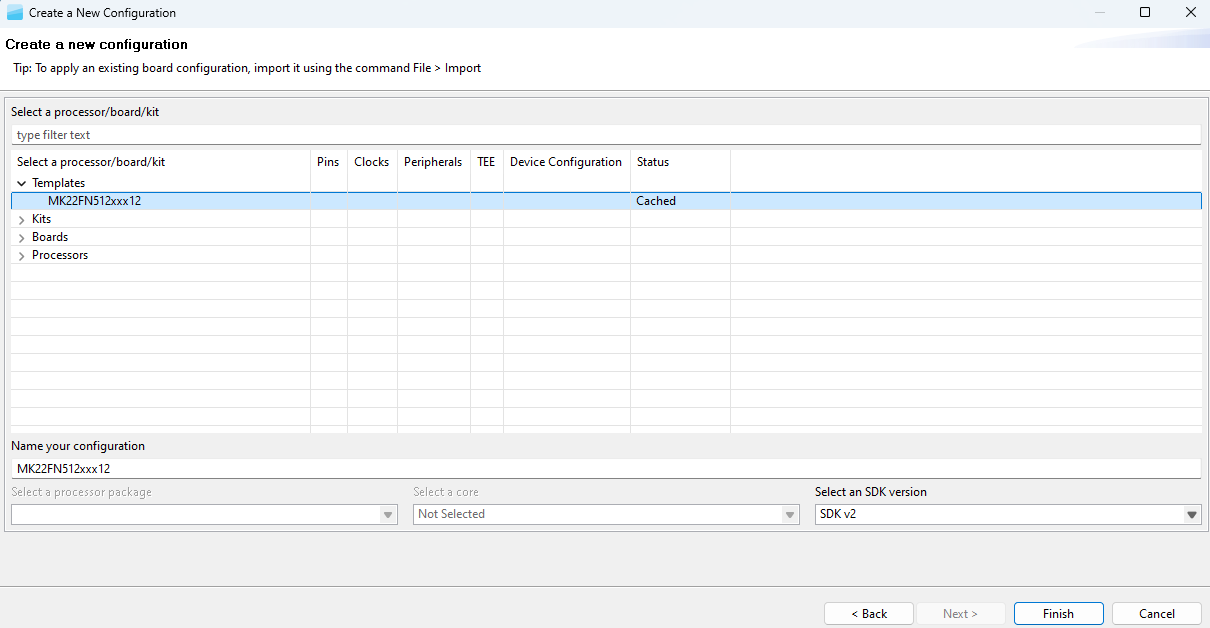
To create a standalone configuration, do the following:
In the Start development wizard select Create a new standalone configuration for processor, board, or kit. Alternatively, in the Menu bar, select File > New.
Click Next.
Select the processor, board, or kit from the list. Note: If you are working offline, you will only see locally saved options. For more information, see the Working offline section.
Name your configuration. Optionally, you can select processor package, core, and SDK version.
Click Finish.
Saving a configuration#
To save your configuration for future use, select File > Save from the Menu bar.
To save a back-up of your configuration, do the following:
In the Menu bar, select File > Save Copy As.
In the dialog, specify the name and destination of the configuration.
Click Save.
Opening an existing configuration#
To open an existing configuration, do the following:
In the Start development wizard, select Open an existing configuration. Alternatively, in the Menu bar, select File > Open.
Click Browse to navigate to your configuration file.
Select the configuration file and click Open.
Optionally, select Always open last configuration to skip the Start development wizard and load the last-saved configuration by default.
User templates#
You can export and store the current configuration as a user template for later use as a reference configuration file.
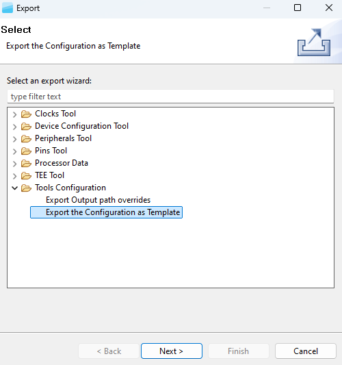
Export template#
The exported template is available in the New Configuration wizard and can be used to create a configuration. You can also define custom labels for pins or identifiers prefixes for #define in the generated code. You can export the configuration by selecting, in the Menu bar, File > Export > Tools Configuration > Export Configuration as Template.
Create a new configuration from the template#
Note: The templates are stored in at the following location on your local hard disk: {$user}/.nxp/{tools_folder}/{version}/templates.
Importing sources#
You can import source code files to use as a basis for further configuration.
Note: You can import only C or DTSI files containing valid YAML configuration blocks generated by the Config Tools. The configuration is reconstructed from the YAML block and the rest of the imported file is ignored.
To import source code files, do the following:
In the Menu bar, select File > Import….
From the list, select MCUXpresso Config Tools > Import Source.
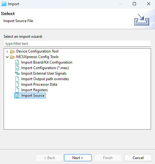
Import Source wizard#
Click Next.
On the next page, click Browse to specify the location of the source file.
Select the source file that you wish to import and click Open.
On the next page, select which functional groups to import (based on tools) by selecting the checkbox in the left column.
Define how to import the functional groups by selecting one of the two available options in the dropdown menu in the right column:
Rename – All files are merged into the current configuration. It imports all the functions only. If the imported function has the same name as an existing one, it is automatically renamed to the indexed one. For example, if
BOARD_InitPinsexists in the configuration then the imported function is renamed toBOARD_InitPins1.Overwrite – All files are merged into the current configuration. It imports all the functions only. If the imported function has the same name as an existing one, then the existing one is replaced with the imported one.
Click Finish.
Importing configuration#
To import an existing configuration from an MEX file, do the following:
In the Menu bar, select File > Import…>.
In the Import wizard, select MCUXpresso Config Tools > Import configuration (*.mex).
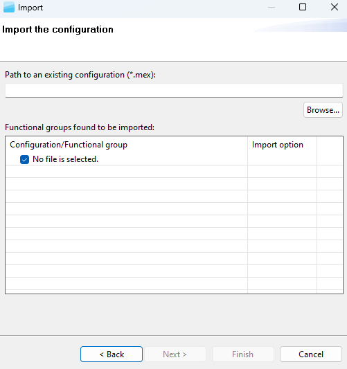
Click Next.
On the next page, click Browse to specify the location of the registers file.
Select the MEX file that you wish to import and click Open.
On the next page, select which functional groups to import (based on tools) by selecting the checkbox in the left column.
Define how to import the functional groups by selecting one of the two available options in the dropdown menu in the right column:
Rename – All files are merged into the current configuration. It imports all the functions only. If the imported function has the same name as an existing one, it is automatically renamed to the indexed one. For example, if
BOARD_InitPinsexists in the configuration then the imported function is renamed toBOARD_InitPins1.Overwrite – All files are merged into the current configuration. It imports all the functions only. If the imported function has the same name as an existing one, then the existing one is replaced with the imported one.
Click Finish.
Import configuration#
Importing Board/Kit Configuration#
Use import settings from default board/kit templates provided within CFG tools data for further configuration.
To import a board/kit configuration, do the following:
In the Menu bar, select File > Import…>.
In the Import wizard, select MCUXpresso Config Tools > Import Board/Kit Configuration.
Click Next.
On the next page, select the board/kit variant from the dropdown menu.
Select which functional groups to import (based on tools) by selecting the checkbox in the left column.
Define how to import the functional groups by selecting one of the two available options in the dropdown menu in the right column:
Rename – All files are merged into the current configuration. It imports all the functions only. If the imported function has the same name as an existing one, it is automatically renamed to the indexed one. For example, if BOARD_InitPins exists in the configuration then the imported function is renamed to BOARD_InitPins1.
Overwrite – All files are merged into the current configuration. It imports all the functions only. If the imported function has the same name as an existing one, then the existing one is replaced with the imported one.
Click Finish.
Importing registers#
You can import a register configuration from a processor memory dump.
Note: Currently, register configuration can be imported into the Clocks tool only.
Note: A processor memory-dump file in the CSV or S19 format is required for importing register configuration.
Import registers#
To import register configuration, do the following:
In the Menu bar, select File > Import…. Alternatively, click the Import Registers Configuration button in the Registers view, or drag-and-drop the memory dump file anywhere in the Registers view area.

Import registers configuration#
In the Import wizard, select MCUXpresso Config Tools > Import Registers.
Click Next.
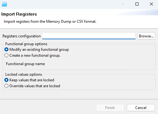
On the next page, click Browse to specify the location of the registers configuration.
Select the registers file you wish to import, and click OK.
By default, the imported register configuration will overwrite the existing functional group. If you want a new functional group to be created instead, select the Create new functional group option button, and specify the functional group name.
Click Finish. Note: All registers are imported from the dump file regardless of their relevance to clock configuration, therefore, the list can contain registers not needed by the Clocks tool.
Restoring configuration from source code#
All Config tools have a possibility of restoring a configuration from the source code. The generated code below contains information about the Clocks tool settings that are used in the tool (block within a comment in YAML format).
The following is an example of the settings information in the generated source code.
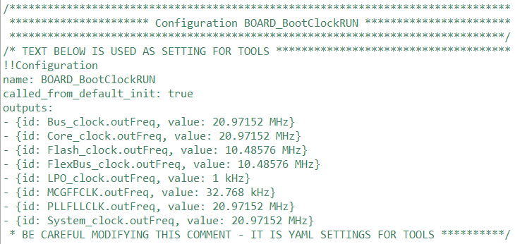
Setting Information in the source code#
If this information is not corrupted, it is possible to reimport the clock settings into the tool using the following steps.
In the Menu bar, select File > Import….
From the list, select MCUXpresso Config Tools > Import Source Files.
Click Next.
Click Browse.
Navigate and select the source file previously produced by one of the Config tools (for example, clock_config.c).
If the settings parse successfully, the clock configurations are added into the current global configuration.
Toolbar#
The toolbar is on the top of the window and includes buttons/menus of frequently used actions common to all tools. See the following sections for more information.
Table Toolbar#
Item |
Description |
|---|---|
Config Tools Overview |
Open the Overview dialog with information about currently used tools. |
Show Problems View |
Open the Problems view. |
Update Code |
Open the update dialog allowing you to update generated peripheral initialization code directly within the specified toolchain project. |
Generate Code |
Regenerate source code when the “Enable Code Preview” preference is disabled. |
Functional group selection |
Select a functional group. A functional group in the Peripherals tool represents a group of peripherals that are initialized as a group. The tool generates a C function for each function group that contains the initialization code. |
Call from default initialization |
Set the current functional group to be initialized by the default initialization function. |
Functional group properties |
Open the Functional group properties dialog to modify name and other properties of the function group. |
Tool selection |
Display icons of individual tools. Use them to switch between tools. |
Undo/Redo |
Undo/Redo last action. |
In addition, the toolbar may contain additional items depending on the selected tool. See the chapters dedicated to individual tools for more information.
Show problems view#
Click the Show Problems View to open/highlight the Problems view and inspect any errors in your configuration. See Problems view for more information.
Button color depends on the issue type. Red indicates the presence of at least one error, yellow indicates the presence of at least one warning.
Update code#
To update the generated code in the related toolchain project, click the Update Code button. In the window, select the tools or files you want to update. If the file is updated automatically, the button is filled with a black square. The reason is displayed in the tooltip.
Note: For multicore projects only the files that are related to the currently selected active core are updated by this command. To get files for other core(s), the export command needs to be used instead.
The project information shows the Project name and path or the path to the mex folder, when the configuration is without a project.
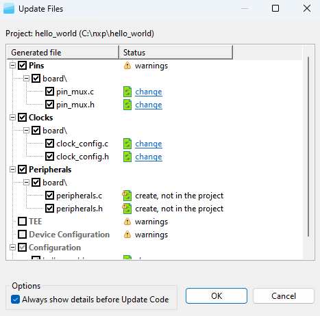
Update Files window#
To inspect the code difference between the versions, click the change link.
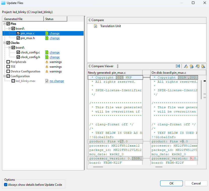
Show differences#
To update the project without opening the Update Files dialog, deselect the Always show details before Update Code checkbox.
To access the Update Code dialog from the Update Code dropdown menu, select Open Update Code Dialog.
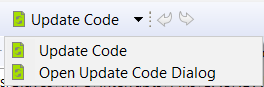
Update Code dropdown menu#
Note: The generated code is always overwritten.
Note: Before the current file is overwritten, it is copied with a BAK extension.
The Update Code action is enabled under the following conditions:
MEX configuration file is saved locally
If the MEX configuration is saved in a toolchain project, the processor selected in the tool matches with the processor selected in the toolchain project
Core is selected (for multicore processors)
Functional groups#
Every Pins/Clocks/Peripherals/TEE configuration can contain several functional groups.
These groups represent functions that will be generated into the source code. Use the dropdown menu to switch between functional groups and configure them.

Functional groups#
You can use two additional buttons to further configure functional groups:
Table Functional Groups#
Icon |
Description |
|---|---|
|
Toggle “Called from default initialization function” feature (in source code) |
|
Opens the Functional group properties window |


Note: Red/orange background indicates errors/warnings in the configuration.
Functional group properties#
In the Functional Group Properties window, you can configure several options for functions and code generation. Each setting is applicable for the selected function. You can specify the generated function name, select the core (for multicore processors only) that is affecting the generated source code, or write a function description (this description is generated in the C file). You can also add, copy, and remove functional groups as needed.
Aside from name and description, you can choose to set parameters for selected functional groups.
Functional group properties are specific for individual Config Tools:
Pins tool:
Set custom #define prefix- If this property is set, the specific custom prefix is used for macros generated into the
pin_mux.h.Otherwise the name of the functional group is used as the prefix.Prefix - The custom prefix string. If it is empty, no prefix is used.
Clocks gate enable - If this property is enabled, the clock gate is enabled in the generated code. The clock gate is needed for access to the peripherals, so have it enabled elsewhere.
Core (for multicore processors only) - Selects the core that is used for executing this function.
Full pins initialization - If this property is set, all features of the pins are fully initialized in the generated function even if matches the after-reset state of the processor. If it is not set, values “Not specified” or “No init” can be selected.
De-initialization function - If this feature is set, an additional function that sets all pins and peripheral signals in this functional group to their after-reset state is generated. The new function has a suffix
_deinitby default.Set custom de-initialization function name- Allows specifying a user-defined name of the de-initialization function.
Clocks tool:
Set custom #define prefix - If this property is set, the custom prefix is used for macros define in
clock_config.h.Otherwise the name of the functional group is used as the prefix.Prefix - The custom prefix string. If it is empty, no prefix is used.
Other settings - The processor-specific settings are specific for each processor. See the tooltips for details.
Peripherals tool:
Prefix - It is used for identifiers, constants, and functions related to the functional group that is used in generated code. If it is not specified, no prefix is used.
TEE tool:
Set custom #define prefix - If this property is checked, the custom prefix is used for macros define in the generated code. Otherwise, the name of the functional group is used as the prefix.
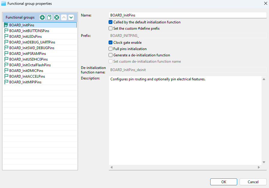
Functional group properties for the Pins tool#
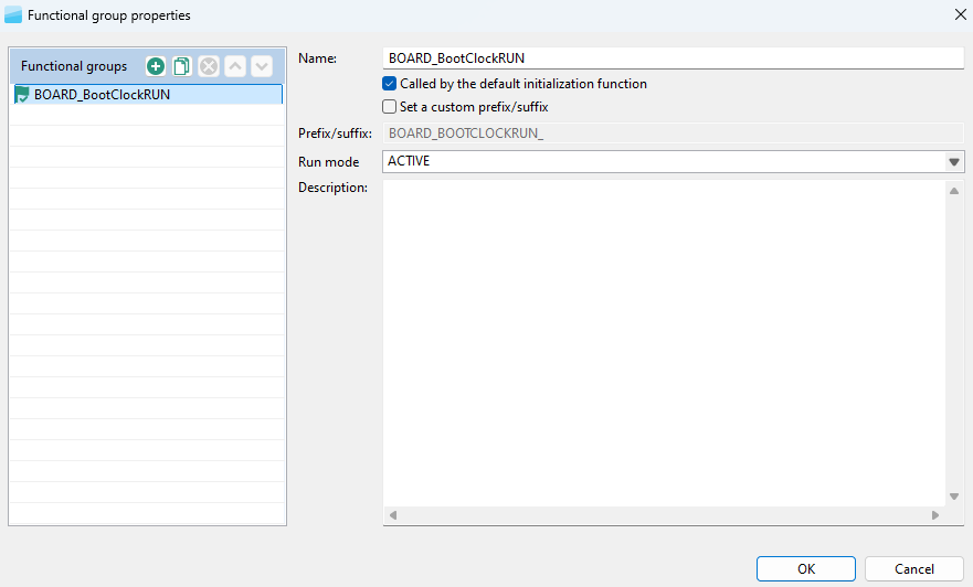
Functional group properties for the Clocks tool#
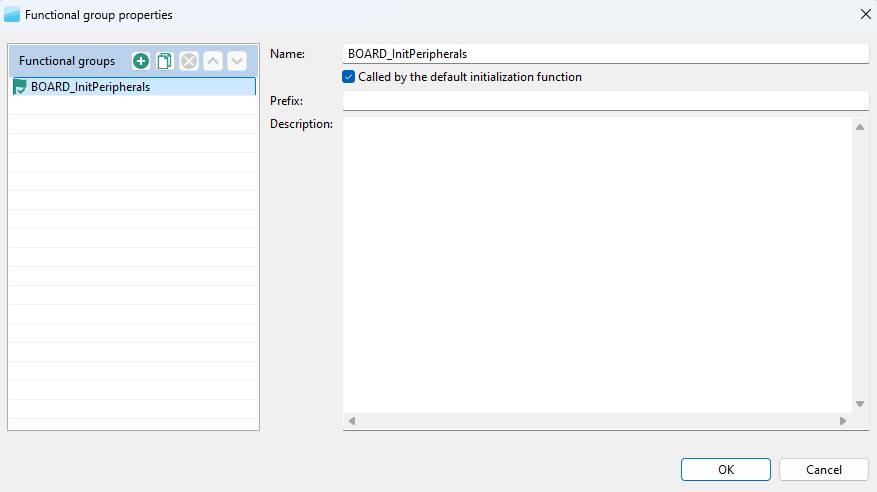
Functional group properties for Peripherals Tool#
Undo/Redo actions#
You can reverse your actions by using the Undo/Redo buttons available in the Toolbar. You can also perform these actions from the Edit menu in the Menu bar.
Table Undo/Redo actions#
Icon |
Description |
|---|---|
|
Cancels the previous action |
|
Cancels the previous undo action |
Selecting the tools#
Buttons on the extreme right-hand side of the toolbar represent available tools. Click the icons to quickly navigate between Pins, Clocks, Peripherals, Device Configuration, and TEE tools.
Status bar#
The status bar is visible at the bottom part of the GUI. The status bar indicates the error and warning state of the currently selected functional group.
Preferences#
To configure preferences in the Preferences dialog, select Edit > Preferences from the Menu bar.
Note: You can restore settings to default by selecting Restore Defaults in the lower right corner of the dialog.
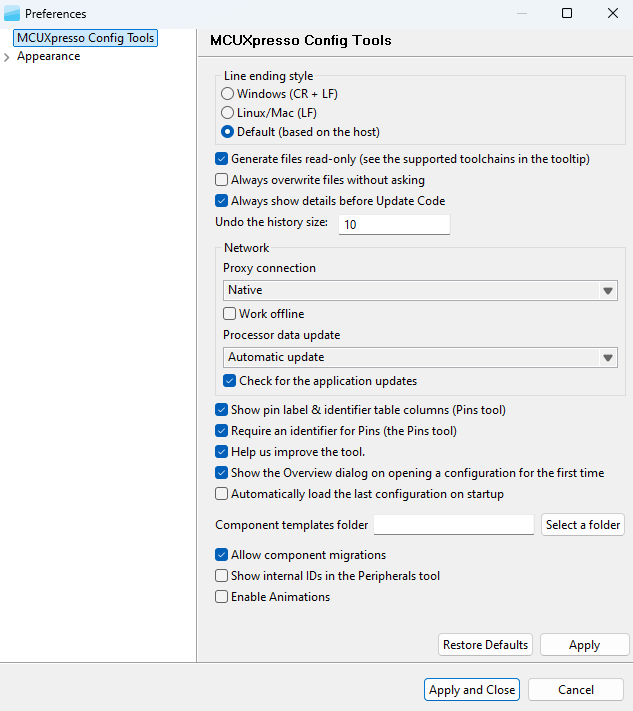
Preferences#
Several settings are available.
Table Preferences#
Item |
Description |
|---|---|
Line ending style |
Select between Windows (CR + LF), Linux/Mac (LF), or Default (based on host). |
Generate files read-only |
Prevent modifying the source files unintentionally. Generated source files are marked as read-only. |
Always overwrite files without asking |
Update existing files automatically, without prompting. |
Always show details before Update Code |
Review changes before the project is updated. |
Undo history size |
Enter the maximum number of steps that can be undone. Enter 0 to disable. |
Proxy connection |
- Direct – Connect directly and avoid a proxy connection. |
Work Offline |
Disable both the connection to NXP cloud and the download of processor/board/kit data. |
Processor data update |
Select from the following options:- Auto Update – Update the processor data automatically. |
Check for application updates |
Check for application updates on a weekly basis |
Show pin label & identifier table columns (Pins Tool) |
Select to show the pin label and the label identifier in the relevant views. |
Require Identifier for Pins (Pins Tool) |
Controls generation of pins “Identifier” related warnings. With this preference enabled, warnings will be generated for bidirectional signals that have no Identifier set. |
Show Overview window on opening configuration for the first time |
Open the Overview dialog on opening the configuration for the first time. |
Help us to improve the tool |
Send device-configuration and tool-use information to NXP. Sending this information to NXP helps fix issues and improve the tools |
Automatically load last configuration on startup |
Avoid the startup window and load the last used configuration instead. |
Component template folder (Peripherals Tool) |
The path to the folder with component templates. Keep empty to use the default path. The default path is to the folder component_templates in the data of the Config tools. |
Allow component migrations (Peripherals Tool) |
When a configuration associated with a toolchain project is open, the peripheral tool automatically checks if the configuration components match the project and suggests a migration if they are not. |
Show internal IDs in Peripherals tool |
When checked, the tooltips in the Peripherals tool will contain internal identifications. |
Enable animations |
Enables animations in the user interface, such as smoother scrolling or opening a drop-down menu. |
Appearance#
In the Appearance window, you can configure the look and feel of the user interface.
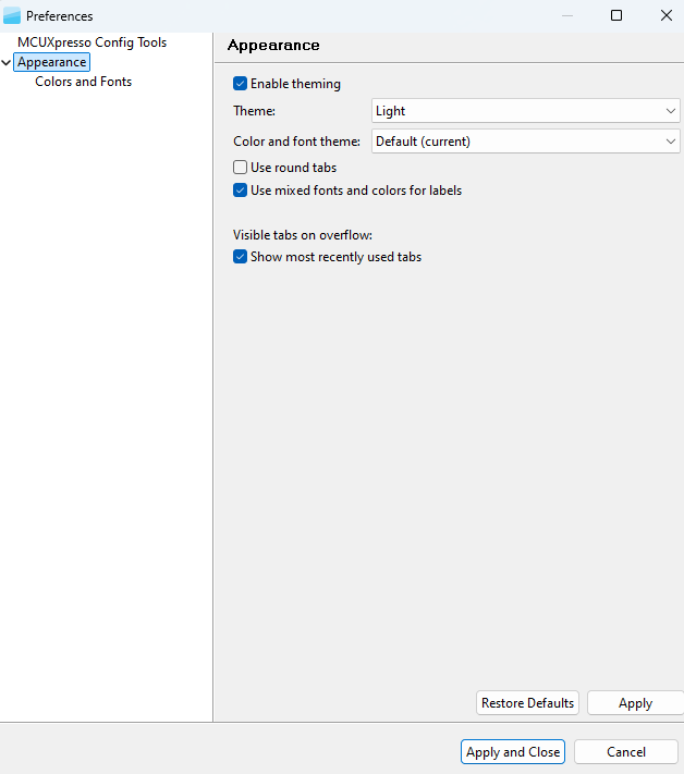
Appearance#
The following options are available:
Enable theming
Theme
Color and Font Theme
Use round tabs
Use mixed fonts and colors for labels
Show most recently used tabs
Also, you can select the Colors and Fonts subwindow to further specify the appearance of interface elements.

Colors and Fonts#
Configuration preferences#
In the Configuration preferences window, you can set your preferences for to the configuration storage file (MEX).
To configure the preferences related to the configuration, select Edit > Configuration Preferences from the Menu bar.
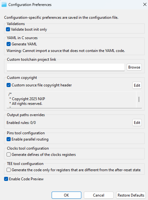
Configuration Preferences#
Several preferences are available.
Table Configuration Preferences#
Item |
Description |
|---|---|
Validate boot init only |
Validate tools’ dependencies only against the ‘boot init’ function group. When selected, dependencies from all functional groups of all tools must be satisfied in the functional groups marked for default initialization. Clearing this option hides warnings in case the user is using complex scenarios with alternating functional groups within the application code. |
Generate YAML |
Generate YAML into C source files. |
Custom toolchain project link |
Set the path to the toolchain project folder, otherwise the default path in the same folder as the configuration is used. An absolute path or a relative path to a saved configuration (MEX) can be used. |
Custom source file copyright header |
Add a custom copyright header to generated source files that do not already contain copyright. |
Generate defines of clock registers |
This feature is disabled by default (Edit->Configuration Preferences). The new |
Generate code only for registers that are different from the after-reset state |
Generate code only for registers that are different from the after-reset state. For projects created in earlier MCUXpresso versions, this option is selected by default. |
Output path overrides |
Rules that are used to override the path of the output files are generated by the tools. They are applied in the Update code and Exports commands. A special dialog allows editing. For more information, see Output path overrides. |
Enable Code Preview |
Controls how the code is generated. When this preference is enabled, code generation is performed automatically after every change in the configuration and the Code Preview is updated accordingly. When this preference is disabled, code generation is stopped, a warning message is displayed in the Code Preview window, and the action can be manually triggered by using one of the available options: |
Warning: When the source does not contain YAML code, it can’t be imported.
Problems view#
The Problems view displays issues in individual tools and in the interdependencies between the tools.
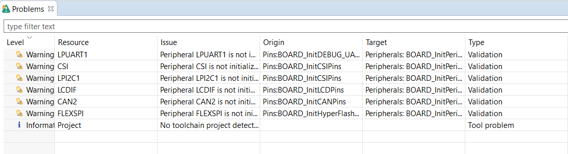
Problems view#
To open the Problems view, click the Show Problems view button in the Toolbar, or select Views > Problems from the Menu bar.
The Problems table contains the following information:
Table Problems view#
Item |
Description |
|---|---|
Level |
Severity of the problem: Information, Warning, or Error. |
Resource |
Resource related to the problem, such as the signal name, the clock signal. |
Issue |
Description of the problem. |
Origin |
Information on the dependency source. |
Target |
Tool that handles the dependency and its resolution. |
Type |
Type of the problem. It is either the validation checking dependencies between tools, or a single tool issue. |
Every issue comes with a context menu accessible by right-clicking the table row. Use this menu to access information about the problem or to apply a quick fix where applicable. You can also copy the rows for later use by right-clicking the row and selecting Copy or by using the Ctrl+C shortcut. You can use the Ctrl+left-click shortcut to add additional rows to the selection.
Note: A quick fix is only available for problems highlighted with the “light bulb” icon.
Filter buttons are available on the right side of the Problems view ribbon.
Table Filter buttons#
Button |
Description |
|---|---|
|
Enables the Validate boot init only preference. See the Configuration preferences section for details. |
|
Filters messages in the Problems view. If selected, only problems for the active tool are displayed. See the Configuration preferences section for details. |


Registers view#
The Registers view lists the registers handled by the tool models. You can see the state of the processor registers that correspond to the current configuration settings and also the state that is in the registers by default after the reset. The values of the registers are displayed in the hexadecimal and binary form. If the value of the register (or bit) is not defined, an interrogation mark “?” is displayed instead of the value.
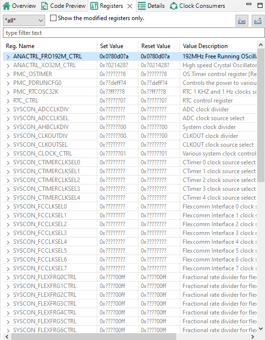
Registers view#
The Registers view contains several items.
Table Registers#
Item |
Description |
|---|---|
Peripheral filter drop-down list |
List the registers only for the selected peripheral. Select all to list registers for all the peripherals. |
Show modified registers only checkbox |
Hide the registers that are left in their after-reset state or are not configured. |
Text filter |
Filter content by text. |
Import/Export registers |
Import/Export registers from/to CSV (Import is available only for the Clocks tool) |
The following table lists the color highlighting styles used in the Registers view.
Table Color codes#
Color |
Description |
|---|---|
Yellow background |
Indicates that the bitfield has been affected by the last change made in the tool. |
Gray text color |
Indicates that the bitfield is not edited and the value is the after-reset value. |
Black text |
Indicates the bit-fields that the tool modifies. |
Note: When the Peripherals tool is active and register initialization components are used, the user can perform manual changes to some of the displayed values.
Note: This view contains registers for the selected tool. The view uses registers as internal parameters but it might not handle all the register writes needed in the code. The register writes are done inside the SDK functions that are called by the generated code. There might be additional registers accessed in the SDK code during the setup process, and such register writes are not known to the tool and are not displayed in the registers view.
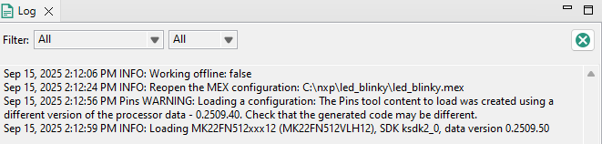
Log view#
The Log view shows user-specific information about MCUXpresso Config Tools operations. The Log view can show up to 100 records across all tools in chronological order.
Each log entry consists of a timestamp, the name of the tool responsible for the entry, severity level, and the actual message. If no tool name is specified, the entry was triggered by shared functionality.
You can filter the content of the Log view using the combo boxes to display only specific tool and/or severity level information. Filters in different tools can be set independently.
Buffered log records are cleared using the clear button. It affects Log views across all tools.
Log view#
Config tools overview#
The Config Tools Overview provides you with general information about your currently active configuration, hardware, and project. It also provides a quick overview of the used/active and unused/inactive tools, generated code, and functional groups. By default, the Config Tools Overview icon is on the left side of the toolbar.
Config Tools Overview opens automatically when you create and open a new configuration. You can disable this behavior in the Preferences.
Config Tools Overview contains several items.
Table Config Tools Overview#
Item |
Description |
|---|---|
Configuration – General Info |
Displays the name of and the path to the MEX file of the current configuration. Click the link to open the folder containing the MEX file. To import additional settings, click the Import additional settings into current configuration button. |
Configuration – HW Info |
Displays the processor, part number, core, and SDK-version information of the current configuration. |
Project |
Displays toolchain project information. |
Pins/Clocks/Peripherals/TEE/Device Configuration |
Displays basic information about the Pins, Clocks, Peripherals, TEE, and Device Configuration tools. |
Note: If you have disabled a tool and want to reopen it, click the tool icon in the upper right corner or select it from the Main Menu. The Config Tools Overview opens automatically.
To enable/disable the tools, click the toggle button. You can navigate to the tools by clicking their icons. The following information about the tools is also available:
Table Config Tools Overview#
Item |
Description |
|---|---|
Generated code |
Contains the list of source-code files. Click the links to open the files in the Code Preview view. |
Functional groups |
Contains the list of the currently active functional groups. To select the groups in the Functional groups tab in the toolbar, select the relevant links. |
To open a tool-specific overview, select Views > Overview from the main menu.
Config Tools Overview#
Note: Unsupported tools are not displayed in the overview.
Config tools snippets#
The Config tools snippets view can be opened in the Config Tools perspective. The snippets view shows snippets collected from the Peripherals tool. The snippets can be categorized. The hierarchy is controlled by the tool. Copy to the clipboard can be done via the toolbar action or context menu.
Note: In the current version, the Config tools snippets view is supported for the Peripherals tool only.