ZPS Configuration Editor
In developing a ZigBee PRO application, certain static configuration is required before the application is built. The ZPS Configuration Editor is used to simplify this configuration. This editor is supplied as an NXP plug-in for Eclipse and is provided in the ZigBee 3.0 SDK (see Section 5.1.2 ZigBee 3.0 SDK). The plug-in is suitable for use with MCUXpresso software.
The ZPS Configuration Editor provides a convenient way to set ZigBee network parameters, such as the properties of the Coordinator, Routers and End Devices (for example, by setting elements of the device descriptors). This chapter describes how to use the ZPS Configuration Editor, as follows: Section 13.1
Section 13.1 Configuration principles describes how the ZigBee network configuration is used in the application build process.
Section 13.2 ZPS Configuration Editor wizard describes how to access the ZPS Configuration Editor wizard.
Section 13.3 Overview of ZPS Configuration Editor Interface provides an overview of the interface provided by the ZPS Configuration Editor.
Section 13.4 Using the ZPS Configuration Editor describes how to use the ZPS Configuration Editor to perform important configuration tasks.
Configuration principles
The build process for a ZigBee PRO application takes a number of configuration files, in addition to the application source file and header file. The following files are generated from the MCUXpresso IDE to feed into the build process:
ZigBee PRO Stack files:
zps_gen.c
zps_gen.h
PDUM files:
pdum_gen.c
pdum_gen.h
Other files:
port.c
portasm.h
portmacro
irq.s

Parent topic:ZPS Configuration Editor
ZPS Configuration Editor wizard
Before you can start to create a new ZigBee PRO stack configuration, the ZPS Configuration Editor plug-in must be installed in MCUXpresso.
To check if the plug-in is already installed, start MCUXpresso and select
File > New > Other from the main menu. Check that a Jennic option exists in the Select a Wizard dialogue box - expanding the Jennic option should show “ZBPro Configuration”, as illustrated in the screenshot below.
Selecting a Wizard
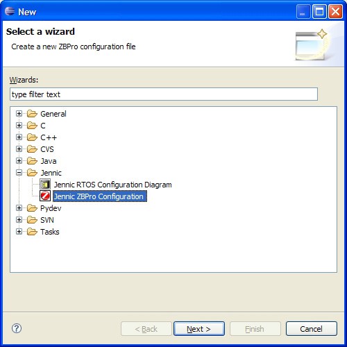
Using the wizard highlighted in the screenshot above, you can start to create a new ZigBee PRO configuration, as described in Section 12.4.1.
If the wizard is not present, install the ZPS Configuration Editor plug-in, which is supplied in the ZigBee 3.0 SDK.
Parent topic:ZPS Configuration Editor
Overview of ZPS Configuration Editor Interface
The ZPS Configuration Editor allows ZigBee network parameters to be configured through an easy-to-use Windows Explorer-style interface. This interface is outlined below.
The parameter values for the whole network are stored in a file with extension .zpscfg, and the ZPS Configuration Editor provides a convenient way to view and edit the contents of this file.
The network parameters are presented in an expandible tree, as shown below.
Network Parameters
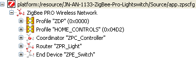
The information under each of these entries is described below.
Entries that sit at the same level in the tree are termed ‘siblings’, while an entry that sits under another entry in the tree (a sub-entry) is termed a ‘child’.
The top level of the tree shows the Extended PAN ID. The next level shows the following siblings:
Entries for the ZigBee application profiles used in the network
Entry for the Coordinator
Entries for the Routers
Entries for the End Devices
Profile
An application profile has a numeric ID and a name. The Profile entry contains child entries for the clusters supported by the profile - each cluster is identified by a numeric ID and a name.
Note: There must be entries for all application profiles supported by the network. An individual device may not use all profiles, although a device can use more than one profile to support multiple features (for example, measurement of temperature, humidity, and light level).
Parent topic:Overview of ZPS Configuration Editor Interface
Coordinator
The Coordinator entry contains a name and a number of associated parameters, mainly related to the APS and NWK layers of the ZigBee PRO stack.
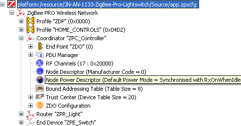
The child entries for the Coordinator are shown above and include the following:
Endpoint entries, one for each endpoint on the Coordinator, with each endpoint having child entries specifying the input and output clusters used (note that each input cluster must be paired with an APDU).
PDU Manager, with child entries specifying the APDUs used.
Channel Mask, specifying the 2.4-GHz band channels to scan when creating the network.
Node Descriptor for the Coordinator.
Node Power Descriptor for the Coordinator.
Parent topic:Overview of ZPS Configuration Editor Interface
Router
Each Router entry contains a name and a number of associated parameters, mainly related to the APS and NWK layers of the ZigBee PRO stack. The child entries for a Router include the following:
Endpoint entries, one for each endpoint on the Router, with each endpoint having child entries specifying input and output clusters used (note that each input cluster must be paired with an APDU).
PDU Manager, with child entries specifying the APDUs used.
Channel Mask, specifying the 2.4-GHz band channels to scan when attempting to join a network.
Node Descriptor for the Router.
Node Power Descriptor for the Router.
Parent topic:Overview of ZPS Configuration Editor Interface
End Device
Each End Device entry contains a name and a number of associated parameters, mainly related to the APS and NWK layers of the ZigBee PRO stack. The child entries for an End Device include the following:
Endpoint entries, one for each endpoint on the End Device, with each endpoint having child entries specifying the input and output clusters used (note that each input cluster must be paired with an APDU).
PDU Manager, with child entries specifying the APDUs used.
Channel Mask, specifying the 2.4-GHz band channels to scan when attempting to join a network.
Node Descriptor for the End Device.
Node Power Descriptor for the End Device.
Parent topic:Overview of ZPS Configuration Editor Interface
Parent topic:ZPS Configuration Editor
Using the ZPS Configuration Editor
Note: This section assumes that you wish to add a ZigBee PRO stack configuration to a project which you have already created in MCUXpresso (in this example, HelloWorld).
Creating a New ZPS Configuration
Step 1: In MCUXpresso, start the ZPS Configuration Editor wizard. To do this, follow the menu path File > New > Other and in the Select a Wizard dialogue box, select “Jennic ZBPro Configuration” and click Next(shown in Figure 13 on page 283).
The New dialogue box opens for the ZBPro Configuration.
New ZPS Configuration
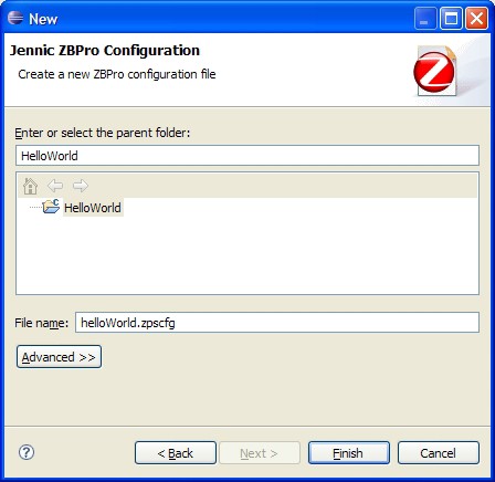
Step 2: Click on your project to select it as the parent folder. In the File namefield, enter a name for the configuration file (keep the extension .zpscfg) and then click Finish.
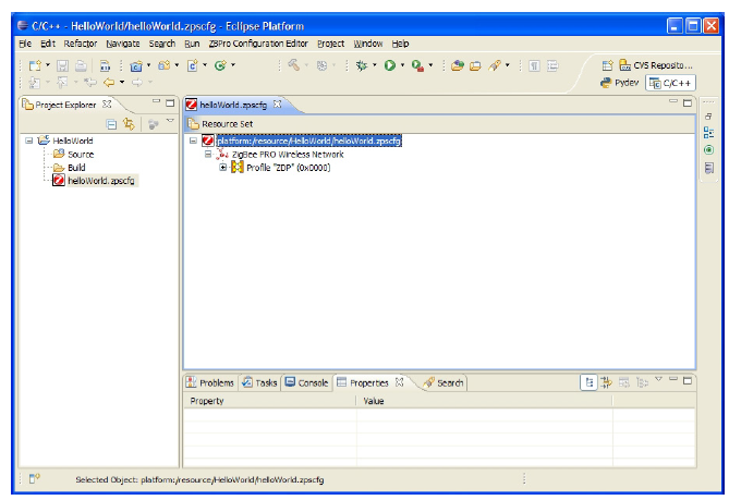
A new configuration (with the default set of parameters) will open in the editor, as shown below.
ZPS Configuration Editor Window
Parent topic:Using the ZPS Configuration Editor
Adding Device Types
Follow the steps below to add devices:
**Step 1:**Right-click on ZigBee PRO Wireless Networkand select New Child > Coordinatorfrom the drop-down menu. This inserts a Coordinator with the minimum necessary child elements.
**Step 2:**Add Routers and End Devices in the same way, as required. The network can only have one Coordinator, but as many different Router or End Device types (that is, running different application features and with different endpoints) as required.
**Step 3:**For each new device, use the Propertiestab (bottom pane) to enter the required top-level parameters. For a sleeping End Device, set Sleepingto True (by right-clicking on the value and using the drop-down box).
Note: To display the advanced properties, click the Advanced tool button to the right of the Properties view tab. Refer to Section 13.4.4 Setting advanced device parameters. These properties are all set to default values and can be left unchanged, unless specific changes are required.
To add a profile
Step 1 Right-click on ZigBee PRO Wireless Network and select New Child > Profile from the drop-down menu. This inserts a profile with no child elements.
Step 2 Edit the properties in the Properties tab to set Name and Id for the new profile.
Parent topic:Adding Device Types
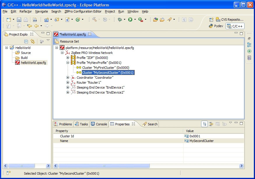
To add clusters to the new profile
Step 1 Right-click on the new profile created above and select New Child > Cluster from the drop-down menu.
Step 2 Edit the properties in the Properties tab to set Nameand Id for the new cluster.
Step 3 Repeat Step 1 and Step 2 to add more clusters, as required.
Parent topic:Adding Device Types
Parent topic:Using the ZPS Configuration Editor
Setting Coordinator properties
To set the channel mask and Node Power descriptor, use the below steps:
Step 1: Expand the Coordinator node in the editor. This reveals the default set of features for the Coordinator, ZDO endpoint, and ZDO servers.
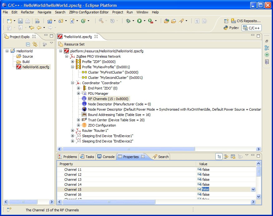
Step 2: Click on the RF Channels element to modify the channel mask.
There are 16 channels available, numbered 11 to 26, which are now shown in the Properties tab. A single channel or a set of channels can be selected for the channel mask, as required.
Step 3: In the Properties tab, set the desired channel(s) to true (by right-clicking on the value and using the drop-down box).
Channel Mask Selection
Step 4: Click to select the Node Power Descriptor.
Step 5: Edit the properties in the Properties tab, as required.
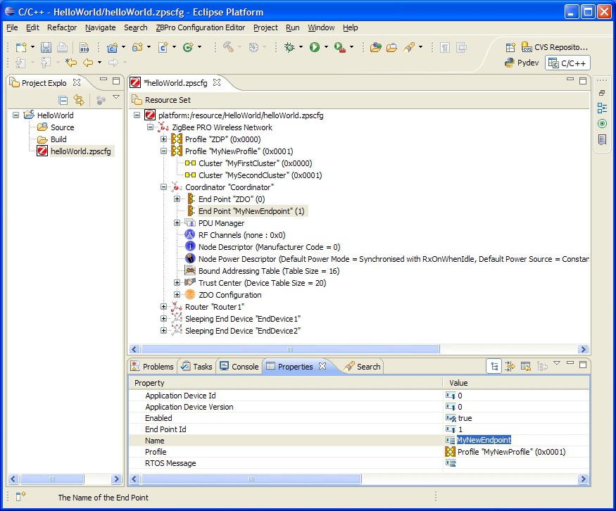
To add a new endpoint
Step 1: Right-click on the Coordinator node and select New Child > End Point from the drop-down menu.
Step 2: Edit the properties in the Properties tab to set Name and Profile for the endpoint (the profile is selected from the drop-down box).
Step 3: Repeat Steps 1 and 2 for as many endpoints as are required.
Endpoint Properties
Parent topic:Setting Coordinator properties
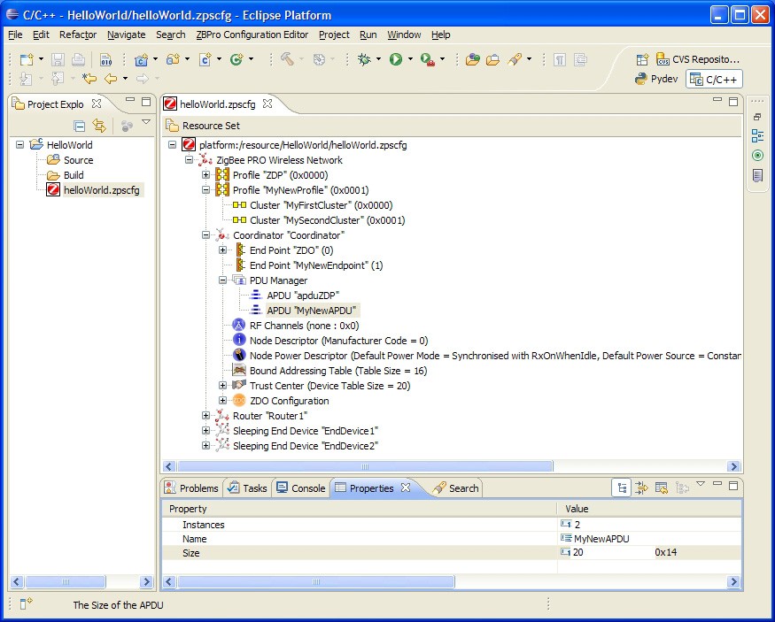
To add an APDU
At least one APDU is required before an endpoint can send or receive data. The same APDU can be used to send and receive data, or different APDUs can be set up for send and receive - this allows control of buffering and memory resources, and is the decision of the application designer.
Step 1: Right-click on PDU Manager and select New Child > APDU from the drop-down menu.
Step 2: Edit the properties in the Properties tab to set Name, Instances (number of) and Size (of each instance - this should be set to the size of the largest APDU to be received).
Parent topic:Setting Coordinator properties
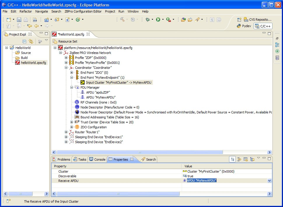
To add input and output clusters to an endpoint
To add input and output clusters to an endpoint
Step 1: Right-click on the endpoint and select New Child > Input Clusteror New Child > Output Cluster, as required, from the drop-down menu.
Step 2: Edit the properties in the Propertiestab to set Cluster- select from the available clusters in the drop-down list.
Step 3: Edit the Rx APDUor Tx APDUproperty to assign an APDU to the cluster - select from the available APDUs in the drop-down list.
To receive data, a cluster must have an assigned APDU. The same cluster can be both an input and output cluster, i.e. it will both send and receive data.
When an endpoint with an output cluster sends data, the receiving endpoint must have an input cluster in order to receive the data, otherwise the stack will reject it and will not notify the receiving endpoint. However, the Default cluster can be added to the endpoint in order to deal with received data that is destined for input clusters not supported by the endpoint (see the Note below this procedure).
Step 4: Repeat Step 1 to Step 3 to add as many clusters as are required for the endpoint.
Step 5: Repeat Step 1 to Step 4 for Routers and End Devices, as required.
Note: In the above procedure, you may want to add the Default cluster (with a Cluster ID of 0xFFFF) as an input cluster. The inclusion of the Default cluster means that received messages that were intended for input clusters not supported by the endpoint will still be passed to the application. The messages must, however, come from defined application profiles, otherwise they are discarded.
Parent topic:Setting Coordinator properties
Parent topic:Using the ZPS Configuration Editor
Setting advanced device parameters
You can set the advanced device parameters (detailed in Section 12.7) for a device as follows:
Step 1: Click on the relevant device (for example, Coordinator) in the Resource Set pane.
Step 2: Click on the Advanced Device Parameters button in the tool bar of the lower pane (indicated below).

Step 3: Edit the relevant parameters in the Properties tab of the lower pane.
Step 4: Save your settings.
The ZigBee PRO R22 version of the stack allows the presence of multiple MAC interfaces. This is to support both 2.4G and 868 MHz frequency bands using the single ZigBee stack. To address this, a MAC interface table needs to be configured in the ZPS Configuration diagram.
The MAC interface list can be found as an option for the node, for example, if you have ZigBee network with a router node. You can select the router node and press the right mouse button to provide the options. The MAC interface list can be found under New Child > Mac Interface List.
After adding the MAC interface list, select and right-click on the MAC interface list to provide the options. The MAC interface can be found under New Child > MAC Interface.
After adding the MAC interface, the properties can be updated. The default is 2.4G. This default can be kept. The “Router Allowed” properties should be set to “true”.
Note: Users should edit the advanced device parameters in order to change the Extended PAN ID (APS Use Extended PAN ID parameter) and the maximum number of children of the Coordinator or Router (Active Neighbor Table Size parameter) from the default values - see Section 6.1.1 and Section 6.1.2.
Parent topic:Using the ZPS Configuration Editor
Parent topic:ZPS Configuration Editor