Getting Started with FRDM-IMX8MPLUS#
Overview#
The FRDM-IMX8MPLUS development board is a low-cost and compact development board featuring the i.MX 8M Plus applications processor. Equipped with an onboard IW612 module, featuring NXP’s Tri-Radio solution with Wi-Fi 6 + Bluetooth 5.4 + 802.15.4, the board is ideal for developing modern Industrial and IoT applications.
This guide helps you quickly get started with the Robotics Edge Platform on your FRDM-IMX8MPLUS board using a pre-built image.
Prerequisites
FRDM-IMX8MPLUS board
USB Type-C cable (for debug UART)
USB Type-C cable (for power)
USB cable (for USB OTG)
microSD card (16 GB or larger recommended)
Host PC (Linux or Windows)
Hardware setup#
Connect USB debug cable#
Connect the supplied USB Type-C male to Type-A male cable to the debug UART port J19. Then, connect the other end of the cable to a host computer.
Two UART connections now appear on the host computer. Use the first port for A53 core system debugging.
Serial port settings:
Baud rate: 115200
Data bits: 8
Parity: None
Stop bits: 1
Flow control: None
Terminal applications:
Linux: Minicom, screen, picocom
Windows: PuTTY, Tera Term
macOS: screen, Serial (app)
Linux Driver Note
To debug under Linux, make sure the CH342F Linux driver is installed.
Board Features#
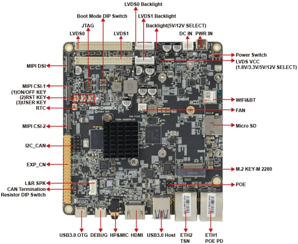
FRDM-IMX8MPLUS Top#
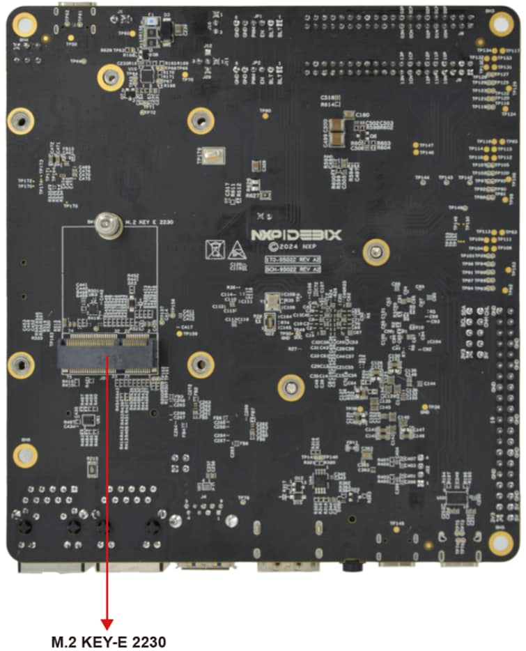
FRDM-IMX8MPLUS bottom#
Boot switch configuration#
SW5[1-4] is the boot configuration switch. For this quick start guide, use the following:
Serial Download Protocol (SDP) mode for flashing:
0001SD card boot after flashing:
0011
Boot Device |
SW5-1 |
SW5-2 |
SW5-3 |
SW5-4 |
|---|---|---|---|---|
USB serial download (for flashing) |
0 |
0 |
0 |
1 |
uSDHC2 SD (normal boot) |
0 |
0 |
1 |
1 |
Switch Position
0 = OFF, 1 = ON
Download Pre-Built Image#
The latest prebuilt images for the FRDM-IMX8MPLUS are available on the Robotics Edge Platform page.
Detailed Package Information
For complete details about the pre-built image package structure, file descriptions, and all available components, please refer to Download pre-built images.
You require two files:
imx-boot-imx8mp-lpddr4-frdm-sd.bin-flash_evk- Bootloaderrobotics-edge-image-full-jazzy-imx8mpevk.rootfs.wic.zst- Root filesystem
Flash the Image Using UUU#
Prerequisites#
Connect the debug UART (J19) to the host machine using a USB Type-C cable.
Connect the USB3.0 OTG (J3) to the host machine using a USB cable.
Insert a microSD card into the board.
Turn off the board.
Set the boot switch
SW5[1-4]to0001(Serial Download Protocol mode).
Important
Make sure that the board is powered OFF before changing the boot switches.
Install uuu Tool#
Before flashing, ensure that the uuu (Universal Update Utility) tool is installed on your host PC.
Install uuu
For detailed installation instructions for Linux and Windows, refer to the Documentation:
Flash to SD card#
Navigate to the directory containing your downloaded image files, then run:
sudo uuu -b sd_all imx-boot-imx8mp-lpddr4-frdm-sd.bin-flash_evk robotics-edge-image-full-jazzy-imx8mpevk.rootfs.wic.zst
uuu.exe -b sd_all imx-boot-imx8mp-lpddr4-frdm-sd.bin-flash_evk robotics-edge-image-full-jazzy-imx8mpevk.rootfs.wic.zst
What happens next:
uuu waits for the USB device to connect.
Power on the board (it should be in SDP mode with switches set to
0001).uuu automatically detects the board.
Flashing progress is displayed.
Wait for a “Success” message.
Flashing Progress
The flashing process typically takes 5-10 minutes depending on your USB connection speed.
Boot the board#
After flashing completes#
Turn off the board.
Change the boot switch
SW5[1-4]to0011(SD card boot).Power on the board.
First Boot#
Open your serial terminal (115200 8N1).
The following are displayed:
U-Boot messages
Linux kernel boot messages
ROS 2 environment initialization
Login prompt
Default Login:
Username:
rootPassword: (press Enter, no password by default)
Robotics Edge ROS2 1.0.0 imx8mpevk ttyLP0
root@imx8mpevk:~#
Board Documentation
For complete board details, refer to the FRDM i.MX 8M Plus product page.