|
ISSDK
1.8
IoT Sensing Software Development Kit
|
|
ISSDK
1.8
IoT Sensing Software Development Kit
|
The fxls8471q_interrupt.c file implements the ISSDK FXLS8471Q sensor driver example demonstration with interrupt mode. More...
#include "pin_mux.h"#include "clock_config.h"#include "board.h"#include "fsl_debug_console.h"#include "issdk_hal.h"#include "gpio_driver.h"#include "fxls8471q_drv.h"#include "Driver_SPI.h"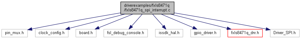
Go to the source code of this file.
Functions | |
| void | fxls8471q_isr (void *pUserData) |
| This is the Sensor Data Ready ISR implementation. More... | |
| int | main (void) |
| This is the The main function implementation. More... | |
Variables | |
| const registerwritelist_t | cFxls8471q_Config_Isr [] |
| const registerreadlist_t | cFxls8471q_Output_Values [] |
| volatile bool | gFxls8471qDataReady = false |
The fxls8471q_interrupt.c file implements the ISSDK FXLS8471Q sensor driver example demonstration with interrupt mode.
Definition in file fxls8471q_spi_interrupt.c.
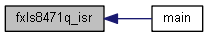
| void fxls8471q_isr | ( | void * | pUserData | ) |
This is the Sensor Data Ready ISR implementation.
This function sets the flag which indicates if a new sample(s) is available for reading.
| [in] | pUserData | This is a void pointer to the instance of the user specific data structure for the ISR. |
Set flag to indicate Sensor has signalled data ready.
Definition at line 71 of file fxls8471q_spi_interrupt.c.
References gFxls8471qDataReady.
Referenced by main().
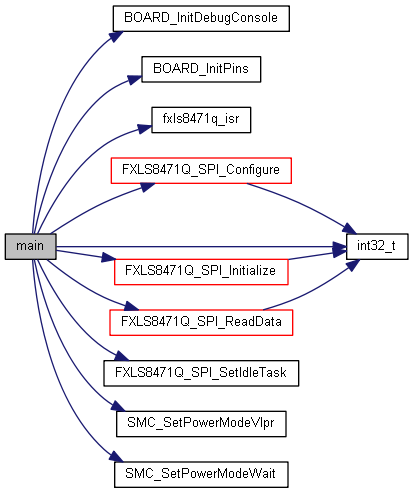
| int main | ( | void | ) |
This is the The main function implementation.
This function invokes board initializes routines, then then brings up the sensor and finally enters an endless loop to continuously read available samples.
| [in] | void | This is no input parameter. |
Initialize the MCU hardware.
Initialize INT1_FXLS8471Q pin used by board
Initialize RGB LED pin used by board
Initialize the SPI driver.
Set the SPI Power mode.
Set the SPI Slave speed.
Initialize the FXLS8471Q sensor driver.
Set the task to be executed while waiting for SPI transactions to complete.
Configure the FXLS8471Q sensor driver.
Clear the data ready flag, it will be set again by the ISR.
Read the raw sensor data from the FXLS8471Q.
Convert the raw sensor data to signed 16-bit container for display to the debug port.
Definition at line 85 of file fxls8471q_spi_interrupt.c.
References fxls8471q_acceldata_t::accel, ASK_USER_TO_RESUME, BOARD_BootClockRUN, BOARD_InitDebugConsole(), BOARD_InitPins(), data, Driver_GPIO_KSDK, FXLS8471_INT1, FXLS8471_SPI_CS, FXLS8471Q_ACCEL_DATA_SIZE, fxls8471q_isr(), FXLS8471Q_SPI_Configure(), FXLS8471Q_SPI_Initialize(), FXLS8471Q_SPI_ReadData(), FXLS8471Q_SPI_SetIdleTask(), FXLS8471Q_WHO_AM_I_WHOAMI_VALUE, gFxls8471qDataReady, GPIO_DIRECTION_IN, GPIO_DIRECTION_OUT, GREEN_LED, int32_t(), GENERIC_DRIVER_GPIO::pin_init, rawData, SENSOR_ERROR_NONE, SMC, SMC_SetPowerModeVlpr(), SMC_SetPowerModeWait(), SPI_S_BAUDRATE, SPI_S_DEVICE_INDEX, SPI_S_DRIVER, SPI_S_SIGNAL_EVENT, status, and GENERIC_DRIVER_GPIO::toggle_pin.
| const registerwritelist_t cFxls8471q_Config_Isr[] |
Prepare the register write list to configure FXLS8471Q in non-FIFO mode.
Definition at line 39 of file fxls8471q_spi_interrupt.c.
| const registerreadlist_t cFxls8471q_Output_Values[] |
Prepare the register read list to read the raw accel data from the FXLS8471Q.
Definition at line 52 of file fxls8471q_spi_interrupt.c.
| volatile bool gFxls8471qDataReady = false |
Definition at line 58 of file fxls8471q_spi_interrupt.c.
Referenced by fxls8471q_isr(), and main().