On-board Debugger#
This section describes the on-board debuggers used on NXP development boards.
On-board debugger MCU-Link#
MCU-Link is a powerful and cost effective debug probe that can be used seamlessly with MCUXpresso IDE, and is also compatible with 3rd party IDEs that support CMSIS-DAP protocol. MCU-Link also includes a USB to UART bridge feature (VCOM) that can be used to provide a serial connection between the target MCU and a host computer. MCU-Link features a high-speed USB interface for high performance debug. MCU-Link is compatible with Windows, MacOS and Linux. A free utility from NXP provides an easy way to install firmware updates.
On-board MCU-Link debugger supports CMSIS-DAP and J-Link firmware. See the table in Default debug interfaces to determine the default debug interface that comes loaded on your specific hardware platform.
The corresponding host driver must be installed before debugging.
For boards with CMSIS-DAP firmware, visit developer.mbed.org/handbook/Windows-serial-configuration and follow the instructions to install the Windows operating system serial driver. If running on Linux OS, this step is not required.
If using J-Link with either a standalone debug pod or MCU-Link, install the J-Link software (drivers and utilities) from www.segger.com/jlink-software.html.
Updating MCU-Link firmware#
This firmware in this debug interface may be updated using the host computer utility called MCU-Link. This typically used when switching between the default debugger protocol (CMSIS-DAP) to SEGGER J-Link, or for updating this firmware with new releases of these. This section contains the steps to reprogram the debug probe firmware.
Note: If MCUXpresso IDE is used and the jumper making DFUlink is installed on the board (JP5 on some boards, but consult the board user manual or schematic for specific jumper number), MCU-Link debug probe boots to DFU mode, and MCUXpresso IDE automatically downloads the CMSIS-DAP firmware to the probe before flash memory programming (after clicking Debug). Using DFU mode ensures that most up-to-date/compatible firmware is used with MCUXpresso IDE.
NXP provides the MCU-Link utility, which is the recommended tool for programming the latest versions of CMSIS-DAP and J-Link firmware onto MCU-Link or NXP boards. The utility can be downloaded from MCU-Link.
These steps show how to update the debugger firmware on your board for Windows operating system.
Install the MCU-Link utility.
Unplug the board’s USB cable.
Make the DFU link (install the jumper labeled DFUlink).
Connect the probe to the host via USB (use Link USB connector).
Open a command shell and call the appropriate script located in the MCU-Link installation directory (
<MCU-Link install dir>).To program CMSIS-DAP debug firmware:
<MCU-Link install dir>/scripts/program_CMSISTo program J-Link debug firmware:
<MCU-Link install dir>/scripts/program_JLINK
Remove DFU link (remove the jumper installed in Step 3).
Repower the board by removing the USB cable and plugging it in again.
On-board debugger LPC-Link#
LPC-Link 2 is an extensible debug probe that can be used seamlessly with MCUXpresso IDE, and is also compatible with 3rd party IDEs that support CMSIS-DAP protocol. MCU-Link also includes a USB to UART bridge feature (VCOM) that can be used to provide a serial connection between the target MCU and a host computer. LPC-Link 2 is compatible with Windows, MacOS and Linux. A free utility from NXP provides an easy way to install firmware updates.
On-board LPC-Link 2 debugger supports CMSIS-DAP and J-Link firmware. See the table in Default debug interfaces to determine the default debug interface that comes loaded on your specific hardware platform.
The corresponding host driver must be installed before debugging.
For boards with CMSIS-DAP firmware, visit developer.mbed.org/handbook/Windows-serial-configuration and follow the instructions to install the Windows operating system serial driver. If running on Linux OS, this step is not required.
If using J-Link with either a standalone debug pod or MCU-Link, install the J-Link software (drivers and utilities) from www.segger.com/jlink-software.html.
Updating LPC-Link firmware#
The LPCXpresso hardware platform comes with a CMSIS-DAP-compatible debug interface (known as LPC-Link2). This firmware in this debug interface may be updated using the host computer utility called LPCScrypt. This typically used when switching between the default debugger protocol (CMSIS-DAP) to SEGGER J-Link, or for updating this firmware with new releases of these. This section contains the steps to reprogram the debug probe firmware.
Note: If MCUXpresso IDE is used and the jumper making DFUlink is installed on the board (JP5 on some boards, but consult the board user manual or schematic for specific jumper number), LPC-Link2 debug probe boots to DFU mode, and MCUXpresso IDE automatically downloads the CMSIS-DAP firmware to the probe before flash memory programming (after clicking Debug). Using DFU mode ensures that most up-to-date/compatible firmware is used with MCUXpresso IDE.
NXP provides the LPCScrypt utility, which is the recommended tool for programming the latest versions of CMSIS-DAP and J-Link firmware onto LPC-Link2 or LPCXpresso boards. The utility can be downloaded from LPCScrypt.
These steps show how to update the debugger firmware on your board for Windows operating system. For Linux OS, follow the instructions described in LPCScrypt user guide (LPCScrypt, select LPCScrypt, and then the documentation tab).
Install the LPCScript utility.
Unplug the board’s USB cable.
Make the DFU link (install the jumper labeled DFUlink).
Connect the probe to the host via USB (use Link USB connector).
Open a command shell and call the appropriate script located in the LPCScrypt installation directory (
<LPCScrypt install dir>).To program CMSIS-DAP debug firmware:
<LPCScrypt install dir>/scripts/program_CMSISTo program J-Link debug firmware:
<LPCScrypt install dir>/scripts/program_JLINK
Remove DFU link (remove the jumper installed in Step 3).
Repower the board by removing the USB cable and plugging it in again.
On-board debugger OpenSDA#
OpenSDA/OpenSDAv2 is a serial and debug adapter that is built into several NXP evaluation boards. It provides a bridge between your computer (or other USB host) and the embedded target processor, which can be used for debugging, flash programming, and serial communication, all over a simple USB cable.
The difference is the firmware implementation: OpenSDA: Programmed with the proprietary P&E Micro developed bootloader. P&E Micro is the default debug interface app. OpenSDAv2: Programmed with the open-sourced CMSIS-DAP/mbed bootloader. CMSIS-DAP is the default debug interface app.
See the table in Default debug interfaces to determine the default debug interface that comes loaded on your specific hardware platform.
The corresponding host driver must be installed before debugging.
For boards with CMSIS-DAP firmware, visit developer.mbed.org/handbook/Windows-serial-configuration and follow the instructions to install the Windows operating system serial driver. If running on Linux OS, this step is not required.
For boards with a P&E Micro interface, see PE micro to download and install the P&E Micro Hardware Interface Drivers package.
Updating OpenSDA firmware#
Any NXP hardware platform that comes with an OpenSDA-compatible debug interface has the ability to update the OpenSDA firmware. This typically means to switch from the default application (either CMSIS-DAP or P&E Micro) to a SEGGER J-Link. This section contains the steps to switch the OpenSDA firmware to a J-Link interface. However, the steps can be applied to restoring the original image also. For reference, OpenSDA firmware files can be found at the links below:
J-Link: Download appropriate image from www.segger.com/opensda.html. Choose the appropriate J-Link binary based on the table in Default debug interfaces. Any OpenSDA v1.0 interface should use the standard OpenSDA download (in other words, the one with no version). For OpenSDA 2.0 or 2.1, select the corresponding binary.
CMSIS-DAP: CMSIS-DAP OpenSDA firmware is available at www.nxp.com/opensda.
P&E Micro: Downloading P&E Micro OpenSDA firmware images requires registration with P&E Micro (www.pemicro.com).
Perform the following steps to update the OpenSDA firmware on your board for Windows and Linux OS users:
Unplug the board’s USB cable.
Press the Reset button on the board. While still holding the button, plug the USB cable back into the board.
When the board re-enumerates, it shows up as a disk drive called MAINTENANCE.
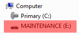
Drag and drop the new firmware image onto the MAINTENANCE drive.
Note: If for any reason the firmware update fails, the board can always reenter maintenance mode by holding down Reset button and power cycling.
These steps show how to update the OpenSDA firmware on your board for Mac OS users.
Unplug the board’s USB cable.
Press the Reset button of the board. While still holding the button, plug the USB cable back into the board.
For boards with OpenSDA v2.0 or v2.1, it shows up as a disk drive called BOOTLOADER in Finder. Boards with OpenSDA v1.0 may or may not show up depending on the bootloader version. If you see the drive in Finder, proceed to the next step. If you do not see the drive in Finder, use a PC with Windows OS 7 or an earlier version to either update the OpenSDA firmware, or update the OpenSDA bootloader to version 1.11 or later. The bootloader update instructions and image can be obtained from P&E Microcomputer website.
For OpenSDA v2.1 and OpenSDA v1.0 (with bootloader 1.11 or later) users, drag the new firmware image onto the BOOTLOADER drive in Finder.
For OpenSDA v2.0 users, type these commands in a Terminal window:
> sudo mount -u -w -o sync /Volumes/BOOTLOADER
> cp -X  <path to update file> /Volumes/BOOTLOADER
Note: If for any reason the firmware update fails, the board can always reenter bootloader mode by holding down the Reset button and power cycling.
On-board debugger Multilink#
An on-board Multilink debug circuit provides a JTAG interface and a power supply input through a single micro-USB connector. It is a hardware interface that allows PC software to debug and program a target processor through its debug port.
The host driver must be installed before debugging.
See PE micro to download and install the P&E Micro Hardware Interface Drivers package.
On-board debugger OSJTAG#
An on-board OSJTAG debug circuit provides a JTAG interface and a power supply input through a single micro-USB connector. It is a hardware interface that allows PC software to debug and program a target processor through its debug port.
The host driver must be installed before debugging.
See PE micro to download and install the P&E Micro Hardware Interface Drivers package.