Appendix#
Example of complete manufacturing flow#
Using a pre-compiled led-demo as an example, a quick start guide is provided in this section to demonstrate the complete manufacturing flow for FlexSPI NOR boot based on MIMXRT1050-EVK board.
Manufacturing process in Development phase#
In development phase, generally the image is unsigned and is used for functional testing.
:heading-offset: 3
Create SB file for HyperFlash programming#
An example to generate the SB file for HyperFlash programming for board is shown as follows.
# The source block assign file name to identifiers
sources {
 myBinFile = extern (0);
}
constants {
    kAbsAddr_Start= 0x60000000;
    kAbsAddr_Ivt = 0x60001000;
    kAbsAddr_App = 0x60002000;
}
# The section block specifies the sequence of boot commands to be written to the SB file
section (0) {
    #1. Prepare Flash option
    # 0xc0233007 is the tag for Serial NOR parameter selection
    # bit [31:28] Tag fixed to 0x0C
    # bit [27:24] Option size fixed to 0
    # bit [23:20] Flash type option
    #             0 - QuadSPI SDR NOR
    #             1 - QUadSPI DDR NOR
    #             2 - HyperFLASH 1V8
    #             3 - HyperFLASH 3V
    #             4 - Macronix Octal DDR
    #             6 - Micron Octal DDR
    #             8 - Adesto EcoXIP DDR
    # bit [19:16] Query pads (Pads used for query Flash Parameters)
    #             0 - 1
    #             2 - 4
    #             3 - 8
    # bit [15:12] CMD pads (Pads used for command)
    #             0 - 1
    #             2 - 4
    #             3 - 8
    # bit [11: 08] fixed to 0
    # bit [07: 04] fixed to 0
    # bit [03: 00] Flash Frequency, device specific
    #
    # In this example, the 0xc0233007 represents:
    #     HyperFLASH 1V8, Query pads: 8 pads, Cmd pads: 8 pads, Frequency: 133MHz
    load 0xc0233007 > 0x2000;
    # Configure HyperFLASH using option a address 0x2000
    enable flexspinor 0x2000;
    #2 Erase flash as needed.(Here only 1MBytes are erased)
    erase 0x60000000..0x60100000;
    #3. Program config block
    # 0xf000000f is the tag to notify Flashloader to program FlexSPI NOR config block to the start of device
    load 0xf000000f > 0x3000;
    # Notify Flashloader to response the option at address 0x3000
    enable flexspinor 0x3000;
    #5. Program image
    load myBinFile > kAbsAddr_Ivt;
}
After the BD file is ready, the next step is to generate the boot_image.sb file that is for MfgTool use later. Here is the example command:
|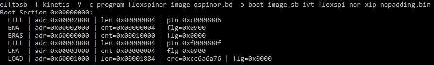
|
After performing above command, the boot_image.sb is generated in elftosb utility folder.
Program Image to Flash using MfgTool#
Here are the steps to program boot image into Flash device
Copy the boot_image.sb file, ivt_flashloader_signed.bin and enable_hab.sb to “<mfgtool_root_dir>/Profiles/device_name/OS Firmware” folder.
Change the “name” under “[List]” to device_name-SecureBoot in cfg.ini file in <mfgtool_root_dir> folder.
Put the device_name-EVK board to Serial Downloader mode by setting SW7 to “1-OFF, 2-ON, 3-OFF, 4-ON”.
Power up device_name-EVK board, and insert USB cable to J9.
Open MfgTool, it will show the detected device like the one shown in Figure 19.
Click “Start”, MfgTool will do manufacturing process and after completion, it will show the status as success as shown in Figure 20 . Click “Stop” and close the MfgTool.
Put the device_name-EVK board to internal boot mode and select HyperFlash as boot device by setting SW7 to “1-OFF, 2-ON, 3-ON, 4-OFF”. Then reset the device to start running the application.
Manufacturing process in Production phase#
In production phase, the image requires to be signed and possibly encrypted. In this case, the device must be configured to HAB closed mode.
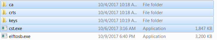
Assuming the PKI tree is ready for cst use, copy “ca”, “crts”, and “keys” folder and cst executable to the folder that holds the elftosb utility executable, as shown below
Copy required key and certificates for signed image generation
Generate signed i.MX RT bootable image#
To generate a bootable image for a specific memory, users need the memory map of the i.MX RT device SoC. Chapter 4, Generate i.MX RT bootable image, provides details for generating a bootable image. Here are the steps to generate signed i.MX RT bootable image using the elftosb utility.
Generate the BD file for boot image generation. The BD file content is showed in the figure below. It is also available in the release package in “<sdk_package>/middleware/mcu-boot/bin/Tools/bd_file/imxrt10xx”<install_dir>/Tools/bd_file/imxrt10xx” folder.
options {
    flags = 0x08;
    startAddress = 0x670000000;
    ivtOffset = 0x1000;
    initialLoadSize = 0x2000;
    //DCDFilePath = "dcd.bin";
    # Note: This is required if the cst and elftsb are not in the same folder
    //cstFolderPath = "path/CSTFolder";
    # Note: This is required if the default entrypoint is not the Reset_Handler
    # Please set the entryPointAddress to base address of Vector table
    //entryPointAddress = 0x670002000;
}
sources {
    elfFile = extern(0);
}
constants {
    SEC_CSF_HEADER = 20;
    SEC_CSF_INSTALL_SRK = 21;
    SEC_CSF_INSTALL_CSFK = 22;
    SEC_CSF_INSTALL_NOCAK = 23;
    SEC_CSF_AUTHENTICATE_CSF = 24;
    SEC_CSF_INSTALL_KEY = 25;
    SEC_CSF_AUTHENTICATE_DATA = 26;
    SEC_CSF_INSTALL_SECRET_KEY = 27;
    SEC_CSF_DECRYPT_DATA = 28;
    SEC_NOP = 29;
    SEC_SET_MID = 30;
    SEC_SET_ENGINE = 31;
    SEC_INIT = 32;
    SEC_UNLOCK = 33;
}
section (SEC_CSF_HEADER;
    Header_Version="4.2",
    Header_HashAlgorithm="sha256",
    Header_Engine="DCP",
    Header_EngineConfiguration=0,
    Header_CertificateFormat="x509",
    Header_SignatureFormat="CMS")
{
}
section (SEC_CSF_INSTALL_SRK;
    InstallSRK_Table="keys/SRK_1_2_3_4_table.bin", // "valid file path"
    InstallSRK_SourceIndex=0)
{
}
section (SEC_CSF_INSTALL_CSFK;
    InstallCSFK_File="crts/CSF1_1_sha256_2048_65537_v3_usr_crt.pem", // "valid file path"
    InstallCSFK_CertificateFormat="x509") // "x509"
{
}
section (SEC_CSF_AUTHENTICATE_CSF)
{
}
section (SEC_CSF_INSTALL_KEY;
    InstallKey_File="crts/IMG1_1_sha256_2048_65537_v3_usr_crt.pem",
    InstallKey_VerificationIndex=0, // Accepts integer or string
    InstallKey_TargetIndex=2) // Accepts integer or string
{
}
section (SEC_CSF_AUTHENTICATE_DATA;
    AuthenticateData_VerificationIndex=2,
    AuthenticateData_Engine="DCP",
    AuthenticateData_EngineConfiguration=0)
{
}
section (SEC_SET_ENGINE;
    SetEngine_HashAlgorithm = "sha256", // "sha1", "Sha256", "sha512"
    SetEngine_Engine = "DCP", // "ANY", "SAHARA", "RTIC", "DCP", "CAAM" and "SW"
    SetEngine_EngineConfiguration = "0") // "valid engine configuration values"
{
}
section (SEC_UNLOCK;
    Unlock_Engine = "SNVS, OCOTP", // "SRTC", "CAAM", SNVS and OCOTP
    Unlock_features = "ZMK WRITE, SRK REVOKE")
{
}
Generate the i.MX RT bootable image using the elftosb utility file.
Here is the example command:
Example command to generate signed boot image
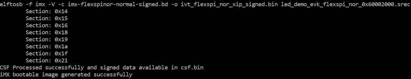
Example command to generate signed boot image
|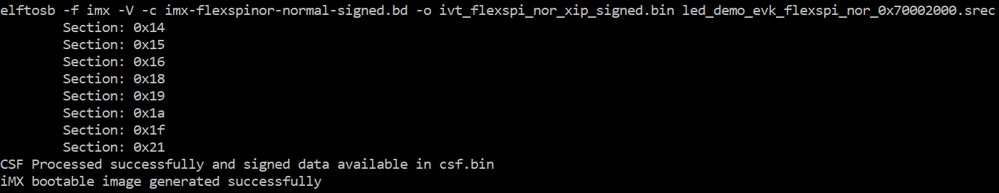
After the above command, two bootable images are generated:
ivt_flexspi_nor_xip_signed.bin
ivt_flexspi_nor_xip_signed_nopadding.bin
The ivt_flexspi_nor_xip_signed_nopadding.bin will be used to generate SB file for HyperFlashQSPI NOR Flash programming in a subsequent section.
Create SB file for Fuse programming#
In the keys folder, there is a file named “SRK_1_2_3_4_fuse.bin”. This is the HASH table for SRK authentication during boot. It must be programmed to fuses to enable secure boot mode.
Below is an example file
Example SRK_1_2_3_4_fuse.bin file

Below is an example BD file which shows the procedure to program fuses. The fuse field is a 32-bit long word data. It will be programmed into the fuses by Flashloader in little-endian mode.
# The source block assign file name to identifiers
sources {
}
constants {
}
# The section block specifies the sequence of boot commands to be written to the SB file
# Note: this is just a template, please update it to actual values in users' project
section (0) {
    # Program SRK table
    load fuse 0xD132E7F1 > 0x18;
    load fuse 0x63CD795E > 0x19;
    load fuse 0x8FF38102 > 0x1A;
    load fuse 0x22A78E77 > 0x1B;
    load fuse 0x01019c82 > 0x1C;
    load fuse 0xFC3AC699 > 0x1D;
    load fuse 0xF2C327A3 > 0x1E;
    load fuse 0xDAC9214E > 0x1F;
    # Program SEC_CONFIG to enable HAB closed mode
    load fuse 0x00000002 > 0x06;
}
The last command in above BD file is used to enable HAB closed mode by setting SEC_CONFIG [1] bit in the fuse to 1.
After BD file is ready, the next step is to create SB file for Fuse programming to enable HAB closed mode.
An example command is shown below:
Example command to generate SB file for Fuse programming
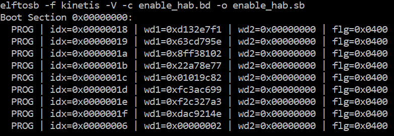
After the command “enable_hab.bd -o enable_hab.sb” in the figure above is executed, a file named “enable_hab.sb” gets generated. It is required in MfgTool for Secure Boot solution.
Create SB file for Image encryption and programming for HyperQSPI Flash#
Following chapter 5, here is an example to generate the SB file for image encryption and programming on HyperQSPIFlash for MIMXRT10506064151020-EVK board.
Refer to the BD file in Section 5.1.3, Generate SB file for FlexSPI NOR Image encryption and programming.
After the BD file is ready, the next step is to generate the SB file. Refer below for an example command.
Example command to generate SB file for FlexSPI NOR image encryption and programming
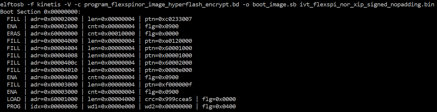
After the command “program_flexspinor_image_hyperflash_encrypt.bd -o boot_image.sb ivt_flexspi_nor_xip_signed_nopadding.bin” in the figure above , a file named “boot_image.sb” is generated in the folder that contains the elftosb utility executable.
Create signed Flashloader image#
The BD file for signed Flashloader image generation is similar as the one in Section 7.1.2.1 Generate signed i.MX RT bootable image.
The only difference is that the startAddress is 0x20000000 and IVTOffset is 0x400.
After the BD file is ready, the next step is to generate i.MX boot image using the elftosb utility. The example command is as below:
Example command for Signed Flashloader image generation
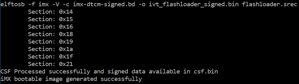
After the command “imx-dtcm-signed.bd -o ivt_flashloader_signed.bin flashloader.srec” in the figure above, two bootable images are generated:
ivt_flashloader_signed.bin
ivt_flashloader_signed_nopadding.bin
The first one is required by MfgTool for Secure Boot.
Generate KeyBlob manually#
Users may need to generate the KeyBlob manually in some cases. The Flashloader supports such usage with blhost.
The KeyBlob must be generated when the device works under HAB closed mode with signed Flashloader application.
Assuming the dek.bin is ready (generated by the elftosb utility during encrypted image generation). Here is an example command to generate KeyBlob block.
Generate KeyBlob using the Flashloader
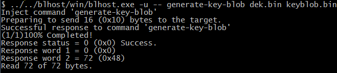
After the command, “blhost.exe -u –generate-key-blob dek.bin keyblob.bin” in figure above is executed, a “keyblob.bin” file gets generated.
Example KeyBlob
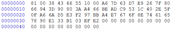
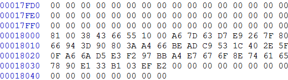
With the encrypted image generated by the elftosb utility and keyblob.bin generated by the Flashloader, it is also feasible to combine the encrypted image and keyblob.bin. Then create a complete encrypted boot image with a Hex Editor. In this example, the KeyBlob offset is 0x18000 in the boot image.
The figure below is an example piece of encrypted image combined by Hex Editor.
Create complete encrypted image using Hex editor