Appendix#
Example of manufacturing flow for RT1060RT1064RT1170-EVK#
Manufacturing process in Development phase#
In development phase, generally the image is unsigned and is used for functional testing.
Templates options for the Manufacturing flow#
To simplify the complexity of the Manufacturing flow, several templates are available in ucl2.xml.
The code block below is an example which is used for programming an SDK XIP project binary into RT1060RT1064RT1170-EVK board. To enable the XiP users need to
Change the “name” item in cfg.ini to “name = MXRT106x-DevBootSerialFlashXiPMXRT1064-DevBootSerialFlashXiPMXRT117x-DevBootFlexSpi1_FlashXiP
Compile the SDK project
Generate the binary file for the project
Rename the binary to boot_image.bin
Copy it to the same folder as ucl2.xml
<!-- This List is for the MCUXpresso SDK XIP demo download via the MfgTool -->
<LIST name="MXRT117x-DevBootFlexSpi1_FlashXiP" desc="Manufacturing with Flashloader">
<!-- Stage 1, load and execute Flashloader -->
    <CMD state="Blhost" type="blhost" body="load-image \"Profiles\\MXRT117x\\OS Firmware\\ivt_flashloader.bin"> Loading and running Flashloader. </CMD>
<!-- Stage 2, Program boot image into external memory using Flashloader -->
    <CMD state="Blhost" type="blhost" body="get-property 1" > Get Property 1. </CMD> <!--Used to test if flashloader runs successfully-->
  <CMD state="Blhost" type="blhost" body="fill-memory 0x20000000 4 0xcf900001"> Select Instance : 1</CMD>
  <CMD state="Blhost" type="blhost" body="configure-memory 0x9 0x20000000"> Enable the FLEXSPI 1 support </CMD>
  <!--Note: This configuration is just an example, please use the correct option for the flash device soldered on the platorm
        See the usage of the configuration option from the System Boot, FLEXSPI NOR API section
  -->
    <CMD state="Blhost" type="blhost" body="fill-memory 0x20000000 4 0xc0000107"> Prepare Flash Configuration option </CMD>
    <CMD state="Blhost" type="blhost" body="configure-memory 0x9 0x20000000"> Configure QuadSPI NOR Flash </CMD>
    <!-- This erase size need to be updated based on the actual boot image size-->
    <CMD state="Blhost" type="blhost" timeout="30000" body="flash-erase-region 0x30000000 0x100000" > Erase 1MBytes </CMD>
    <CMD state="Blhost" type="blhost" timeout="15000" body="write-memory 0x30000400 \"Profiles\\MXRT117x\\OS Firmware\\boot_image.bin\"" > Program Boot Image. </CMD>
    <CMD state="Blhost" type="blhost" body="Update Completed!">Done</CMD>
</LIST>
<LIST name="MXRT106x4-DevBootSerialFlashXiP" desc="Manufacturing with Flashloader">
<!-- Stage 1, load and execute Flashloader -->
    <CMD state="BootStrap" type="boot" body="BootStrap" file="ivt_flashloader.bin">
        Loading Flashloader. </CMD>
    <CMD state="BootStrap" type="jump" onError = "ignore"> Jumping to Flashloader. </CMD>
<!-- Stage 2, Program boot image into external memory using Flashloader -->
    <CMD state="Blhost" type="blhost" body="get-property 1" > Get Property 1. </CMD>
    <!--Used to test if flashloader runs successfully-->
    <CMD state="Blhost" type="blhost" body="fill-memory 0x2000 4 0xc0000007">
        Prepare Flash Configuration option </CMD>
    <CMD state="Blhost" type="blhost" body="configure-memory 0x9 0x2000">
        Configure QuadSPI NOR Flash </CMD>
    <!-- This erase size need to be updated based on the actual boot image size-->
    <CMD state="Blhost" type="blhost" timeout="30000" body="flash-erase-region
     0x670000000 0x100000" > Erase 1MBytes </CMD>
    <CMD state="Blhost" type="blhost" timeout="15000" body="write-memory 0x670000000
     \"Profiles\\MXRT106x\\OS Firmware\\boot_image.bin\"" > Program Boot Image. </CMD>
    <CMD state="Blhost" type="blhost" body="Update Completed!">Done</CMD>
</LIST>
The code block below is an example which is used for programming the SDK XIP project binary into RT1060RT1064RT1170-EVK board with other FLASH device. Users may need to modify the 0xc00000070xc0000107** configuration option for actual soldered FLASH devices. See chapter “External memory support” in MCU Flashloader Reference Manual for more details.
To enable the option, users need to
Change the “name” item in cfg.ini to *”name = MXRT106xMXRT1064-DevBootSerialFlashXiP_NoConfigBlock”*MXRT117x-DevBootFlexSpi1_FlashXiP_NoConfigBlock”
Compile the SDK project
Generate the binary file for the project
Rename the binary to boot_image.bin
Copy it to the same folder as ucl2.xml
<!-- This List is for the MCUXpresso SDK XIP demo download via the MfgTool -->
<LIST name="MXRT117x-DevBootFlexSpi1_FlashXiP_NoConfigBlock" desc="Manufacturing with Flashloader">
<!-- Stage 1, load and execute Flashloader -->
    <CMD state="Blhost" type="blhost" body="load-image \"Profiles\\MXRT117x\\OS Firmware\\ivt_flashloader.bin"> Loading and running Flashloader. </CMD>
<!-- Stage 2, Program boot image into external memory using Flashloader -->
    <CMD state="Blhost" type="blhost" body="get-property 1" > Get Property 1. </CMD> <!--Used to test if flashloader runs successfully-->
  <CMD state="Blhost" type="blhost" body="fill-memory 0x20000000 4 0xcf900001"> Select Instance : 1</CMD>
  <CMD state="Blhost" type="blhost" body="configure-memory 0x9 0x20000000"> Enable the FLEXSPI 1 support </CMD>
  <!--Note: This configuration is just an example, please use the correct option for the flash device soldered on the platorm
        See the usage of the configuration option from the System Boot, FLEXSPI NOR API section
  -->
    <CMD state="Blhost" type="blhost" body="fill-memory 0x20000000 4 0xc0000107"> Prepare Flash Configuration option </CMD>
    <CMD state="Blhost" type="blhost" body="configure-memory 0x9 0x20000000"> Configure QuadSPI NOR Flash </CMD>
    <!-- This erase size need to be updated based on the actual boot image size-->
    <CMD state="Blhost" type="blhost" timeout="30000" body="flash-erase-region 0x30000000 0x100000" > Erase 1MBytes </CMD>
  <!-- Program the Flash Config block to the FLASH ofset 0x400 automatically -->
  <CMD state="Blhost" type="blhost" body="fill-memory 0x20000000 4 0xf000000f"> Prepare Flash Configuration option </CMD>
    <CMD state="Blhost" type="blhost" body="configure-memory 0x9 0x20000000"> Configure QuadSPI NOR Flash </CMD>
    <CMD state="Blhost" type="blhost" timeout="15000" body="write-memory 0x30000400 \"Profiles\\MXRT117x\\OS Firmware\\boot_image.bin\"" > Program Boot Image. </CMD>
    <CMD state="Blhost" type="blhost" body="Update Completed!">Done</CMD>
</LIST>
<LIST name="MXRT106x4-DevBootSerialFlashXiP_NoConfigBlock"
      desc="Manufacturing with Flashloader">
<!-- Stage 1, load and execute Flashloader -->
    <CMD state="BootStrap" type="boot" body="BootStrap" file="ivt_flashloader.bin">
        Loading Flashloader. </CMD>
    <CMD state="BootStrap" type="jump" onError = "ignore">
        Jumping to Flashloader. </CMD>
<!-- Stage 2, Program boot image into external memory using Flashloader -->
    <CMD state="Blhost" type="blhost" body="get-property 1" > Get Property 1. </CMD>
    <!--Used to test if flashloader runs successfully-->
    <CMD state="Blhost" type="blhost" body="fill-memory 0x2000 4 0xc0000007">
        Prepare Flash Configuration option </CMD>
    <CMD state="Blhost" type="blhost" body="configure-memory 0x9 0x2000">
        Configure Serial FLASH </CMD>
    <!-- This erase size need to be updated based on the actual boot image size-->
    <CMD state="Blhost" type="blhost" timeout="30000" body="flash-erase-region
     0x670000000 0x10000" > Erase 64KBytes </CMD>
    <CMD state="Blhost" type="blhost" body="fill-memory 0x3000 4 0xf000000f">
        Prepare Magic number for config block programming </CMD>
    <CMD state="Blhost" type="blhost" body="configure-memory 0x9 0x3000">
        Write auto-generated config block to QuadSPI NOR Flash </CMD>
    <CMD state="Blhost" type="blhost" timeout="15000" body="write-memory 0x670001000
     \"Profiles\\MXRT106x\\OS Firmware\\boot_image.bin\"" > Program Boot Image. </CMD>
    <CMD state="Blhost" type="blhost" body="Update Completed!">Done</CMD>
</LIST>
The code block below is an example which is used for programming the SDK XIP project binary without FCB and Boot data information. Users may need to modify the 0xc0000007in the configuration option for actual soldered FLASH device. See chapter “External memory support” in MCU Flashloader Reference Manual for more details.
To enable the option, users need to
Change the “name” item in cfg.ini to “name = MXRT106x4-DevBootSerialFlashXiP_NoConfigBlockBootData”
Compile the SDK project
Generate the binary file for the project
Rename the binary to boot_image.bin
Copy it to the same folder as ucl2.xml
Note:
The application start address must be 0x670002000 for this example.
The default image size is configured to 4 Mbytes in the ivt_bootdata_0x6000_2000. It fits most application requirement. Users can modify offset 0x24-0x27 in this file to change the image size to meet the actual requirement.
<LIST name="MXRT106x4-DevBootSerialFlashXiP_NoConfigBlockBootData"
      desc="Manufacturing with Flashloader">
<!-- Stage 1, load and execute Flashloader -->
    <CMD state="BootStrap" type="boot" body="BootStrap" file="ivt_flashloader.bin">
        Loading Flashloader. </CMD>
    <CMD state="BootStrap" type="jump" onError = "ignore"> Jumping to Flashloader. </CMD>
<!-- Stage 2, Program boot image into external memory using Flashloader -->
    <CMD state="Blhost" type="blhost" body="get-property 1" > Get Property 1. </CMD>
    <!--Used to test if flashloader runs successfully-->
    <CMD state="Blhost" type="blhost" body="fill-memory 0x2000 4 0xc0000007">
        Prepare Flash Configuration option </CMD>
    <CMD state="Blhost" type="blhost" body="configure-memory 0x9 0x2000">
        Configure Serial FLASH </CMD>
    <!-- This erase size need to be updated based on the actual boot image size-->
    <CMD state="Blhost" type="blhost" timeout="30000" body="flash-erase-region
     0x670000000 0x100000" > Erase 1MBytes </CMD>
    <CMD state="Blhost" type="blhost" body="fill-memory 0x3000 4 0xf000000f">
        Prepare Magic nubmer for config block programming </CMD>
    <CMD state="Blhost" type="blhost" body="configure-memory 0x9 0x3000">
        Write auto-generated config block to QuadSPI NOR Flash </CMD>
    <CMD state="Blhost" type="blhost" timeout="15000" body="write-memory 0x670001000
     \"Profiles\\MXRT106x\\OS Firmware\\ivt_bootdata.bin\"" >
        Program IVT and Boot data. </CMD>
    <CMD state="Blhost" type="blhost" timeout="15000" body="write-memory 0x670002000
     \"Profiles\\MXRT106x\\OS Firmware\\boot_image.bin\"" > Program Boot Image. </CMD>
    <CMD state="Blhost" type="blhost" body="Update Completed!">Done</CMD>
</LIST>
The code block below is an example which is used for programming the non-XIP ITCM image which is stored on the FlexSPI NOR. Users may need to modify the 0xc0000007to the configuration option for actual soldered FLASH devices. See chapter “External memory support” in MCU Flashloader Reference Manual for more details.
To enable the option, users need to
Change the “name” item in cfg.ini to “name = MXRT106x4-DevBootSerialFlashXiP_ITCM_0x0000_1400”
Compile the SDK project
Generate the binary file for the project
Rename the binary to boot_image.bin
Copy it to the same folder as ucl2.xml
Note:
The application start address must be 0x1400 for this option. The actual boot image starts from address 0x1000, the IVT starts at offset 0x100, and application starts at offset 0x1300.
The default image size is configured to 127 Kbytes in the ivt_bootdata_0x0000_1400. This is because it cannot exceed the default ITCM size(128KB).
<LIST name="MXRT106x4-DevBootSerialFlashNonXiP_ITCM_0x0000_1400"
      desc="Manufacturing with Flashloader">
<!-- Stage 1, load and execute Flashloader -->
    <CMD state="BootStrap" type="boot" body="BootStrap" file="ivt_flashloader.bin">
        Loading Flashloader. </CMD>
    <CMD state="BootStrap" type="jump" onError = "ignore"> Jumping to Flashloader. </CMD>
<!-- Stage 2, Program boot image into external memory using Flashloader -->
    <CMD state="Blhost" type="blhost" body="get-property 1" > Get Property 1. </CMD>
    <!--Used to test if flashloader runs successfully-->
    <CMD state="Blhost" type="blhost" body="fill-memory 0x2000 4 0xc0000007">
        Prepare Flash Configuration option </CMD>
    <CMD state="Blhost" type="blhost" body="configure-memory 0x9 0x2000">
        Configure Serial FLASH </CMD>
    <!-- This erase size need to be updated based on the actual boot image size-->
    <CMD state="Blhost" type="blhost" timeout="30000" body="flash-erase-region
     0x670000000 0x80000" > Erase 512KBytes </CMD>
    <CMD state="Blhost" type="blhost" body="fill-memory 0x3000 4 0xf000000f">
        Prepare Magic nubmer for config block programming </CMD>
    <CMD state="Blhost" type="blhost" body="configure-memory 0x9 0x3000">
        Write auto-generated config block to QuadSPI NOR Flash </CMD>
    <CMD state="Blhost" type="blhost" timeout="15000" body="write-memory 0x670001000
     \"Profiles\\MXRT106x\\OS Firmware\\ivt_bootdata_0x0000_1400.bin\"" >
        Program IVT, Boot data. </CMD>
    <CMD state="Blhost" type="blhost" timeout="15000" body="write-memory 0x670001300
     \"Profiles\\MXRT106x\\OS Firmware\\boot_image.bin\"" > Program Boot Image. </CMD>
    <CMD state="Blhost" type="blhost" body="Update Completed!">Done</CMD>
</LIST>
The code block below is an example which is used for programming the non-XIP DTCM image which is stored on the FlexSPI NOR. Users may need to modify the 0xc0000007to the configuration option for actual soldered FLASH devices. See Chapter “External memory support” in the MCU Flashloader Reference Manual for more details.
To enable the option, users need to
Change the “name” item in cfg.ini to “name = MXRT106x4-DevBootSerialFlash XiP_DTCM_0x2000_2000”
Compile the SDK project
Generate the binary file for the project
Rename the binary to boot_image.bin
Copy it to the same folder as ucl2.xml
Note:
The application start address must be 0x20002000 for this option. The actual boot image starts from address 0x20000000, the IVT starts at offset 0x1000, and application starts at offset 0x2000.
The default image size is configured to 128 Kbytes in the ivt_bootdata_0x2000_2000. This is because it cannot exceed the default DTCM size(128 KB).
<LIST name="MXRT106x4-DevBootSerialFlashNonXiP_DTCM_0x2000_2000"
      desc="Manufacturing with Flashloader">
<!-- Stage 1, load and execute Flashloader -->
    <CMD state="BootStrap" type="boot" body="BootStrap" file="ivt_flashloader.bin">
        Loading Flashloader. </CMD>
    <CMD state="BootStrap" type="jump" onError = "ignore"> Jumping to Flashloader. </CMD>
<!-- Stage 2, Program boot image into external memory using Flashloader -->
    <CMD state="Blhost" type="blhost" body="get-property 1" > Get Property 1. </CMD>
    <!--Used to test if flashloader runs successfully-->
    <CMD state="Blhost" type="blhost" body="fill-memory 0x2000 4 0xc0000007">
        Prepare Flash Configuration option </CMD>
    <CMD state="Blhost" type="blhost" body="configure-memory 0x9 0x2000">
        Configure Serial FLASH </CMD>
    <!-- This erase size need to be updated based on the actual boot image size-->
    <CMD state="Blhost" type="blhost" timeout="30000" body="flash-erase-region
     0x670000000 0x80000" > Erase 512KBytes </CMD>
    <CMD state="Blhost" type="blhost" body="fill-memory 0x3000 4 0xf000000f">
        Prepare Magic nubmer for config block programming </CMD>
    <CMD state="Blhost" type="blhost" body="configure-memory 0x9 0x3000">
        Write auto-generated config block to QuadSPI NOR Flash </CMD>
    <CMD state="Blhost" type="blhost" timeout="15000" body="write-memory 0x670001000
     \"Profiles\\MXRT106x\\OS Firmware\\ivt_bootdata_0x2000_2000.bin\"" >
        Program IVT, Boot data. </CMD>
    <CMD state="Blhost" type="blhost" timeout="15000" body="write-memory 0x670002000
     \"Profiles\\MXRT106x\\OS Firmware\\boot_image.bin\"" > Program Boot Image. </CMD>
    <CMD state="Blhost" type="blhost" body="Update Completed!">Done</CMD>
</LIST>
The code block below is an example which is used for programming the non-XIP OCRAM image which is stored on the FlexSPI NOR. Users may need to modify the 0xc0000007to the configuration option for actual soldered FLASH devices. See chapter “External memory support” in MCU Flashloader Reference Manual for more details.
To enable the option, users need to
Change the name item in cfg.ini to “name = MXRT106x4-DevBootSerialFlashNonXiP_OCRAM_0x2020_a000”
Compile the SDK project
Generate the binary file for the project
Rename the binary to boot_image.bin
Copy it to the same folder as ucl2.xml
Note:
The application start address must be 0x2020a000 for this option. The actual boot image starts from address 0x20208000, the IVT starts at offset 0x1000, and application starts at offset 0x2000.
The default image size is configured to 736Kbytes in the ivt_bootdata_0x2020_a000. This is because it cannot exceed the default OCRAM size (768KB - 32KB Reserved RAM size for ROM use).
<LIST name="MXRT106x4-DevBootSerialFlashNonXiP_OCRAM_0x2020_a000"
      desc="Manufacturing with Flashloader">
<!-- Stage 1, load and execute Flashloader -->
    <CMD state="BootStrap" type="boot" body="BootStrap" file="ivt_flashloader.bin">
        Loading Flashloader. </CMD>
    <CMD state="BootStrap" type="jump" onError = "ignore"> Jumping to Flashloader. </CMD>
<!-- Stage 2, Program boot image into external memory using Flashloader -->
    <CMD state="Blhost" type="blhost" body="get-property 1" > Get Property 1. </CMD>
    <!--Used to test if flashloader runs successfully-->
    <CMD state="Blhost" type="blhost" body="fill-memory 0x2000 4 0xc0000007">
        Prepare Flash Configuration option </CMD>
    <CMD state="Blhost" type="blhost" body="configure-memory 0x9 0x2000">
        Configure Serial FLASH </CMD>
    <!-- This erase size need to be updated based on the actual boot image size-->
    <CMD state="Blhost" type="blhost" timeout="30000" body="flash-erase-region
     0x70000000 0x80000" > Erase 512KBytes </CMD>
    <CMD state="Blhost" type="blhost" body="fill-memory 0x3000 4 0xf000000f">
        Prepare Magic nubmer for config block programming </CMD>
    <CMD state="Blhost" type="blhost" body="configure-memory 0x9 0x3000">
        Write auto-generated config block to QuadSPI NOR Flash </CMD>
    <CMD state="Blhost" type="blhost" timeout="15000" body="write-memory 0x70001000
     \"Profiles\\MXRT106x\\OS Firmware\\ivt_bootdata_0x2020_a000.bin\"" >
        Program IVT, Boot data. </CMD>
    <CMD state="Blhost" type="blhost" timeout="15000" body="write-memory 0x70002000
     \"Profiles\\MXRT106x\\OS Firmware\\boot_image.bin\"" > Program Boot Image. </CMD>
    <CMD state="Blhost" type="blhost" body="Update Completed!">Done</CMD>
</LIST>
The code block below is an example which is used for general purpose. SB format boot image, boot_image.sb, needs to be created and copied to the same folder as ucl2.mxl. Details of creating SB format boot image can be found in chapter 4 and chapter 5.
<LIST name="MXRT106x4-DevBoot" desc="Manufacturing with Flashloader">
<!-- Stage 1, load and execute Flashloader -->
    <CMD state="BootStrap" type="boot" body="BootStrap" file="ivt_flashloader.bin">
        Loading Flashloader. </CMD>
    <CMD state="BootStrap" type="jump" onError = "ignore"> Jumping to Flashloader. </CMD>
<!-- Stage 2, Program boot image into external memory using Flashloader -->
    <CMD state="Blhost" type="blhost" body="get-property 1" > Get Property 1. </CMD>
    <!--Used to test if flashloader runs successfully-->
    <CMD state="Blhost" type="blhost" timeout="15000" body="receive-sb-file
     \"Profiles\\MXRT106X\\OS Firmware\\boot_image.sb\"" > Program Boot image </CMD>
    <CMD state="Blhost" type="blhost" body="Update Completed!">Done</CMD>
</LIST>
The code block below is an example which is used for general purpose in production phase. SB format boot image, boot_image.sb, needs to be created and copied to the same folder as ucl2.mxl. Details of creating SB format boot image can be found in chapter 4 and chapter 5.
<LIST name="MXRT106x4-SecureBoot" desc="Boot Signed Flashloader">
<!-- Stage 1, load and execute Flashloader -->
    <CMD state="BootStrap" type="boot" body="BootStrap" file="ivt_flashloader_signed.bin" >
        Loading Flashloader. </CMD>
    <CMD state="BootStrap" type="jump" onError="ignore"> Jumping to Flashloader. </CMD>
<!-- Stage 2, Enable HAB closed mode using Flashloader -->
    <CMD state="Blhost" type="blhost" body="get-property 1" ifhab="Open" >
        Get Property 1. </CMD> <!--Used to test if flashloader runs successfully-->
    <CMD state="Blhost" type="blhost" body="receive-sb-file \"Profiles\\MXRT106X\\OS
     Firmware\\enable_hab.sb\"" ifhab="Open" > Program Boot Image. </CMD>
    <CMD state="Blhost" type="blhost" body="reset" ifhab="Open"> Reset. </CMD>
    <!--Reset device to enable HAB Close Mode-->
<!-- Stage 3, Program signed image into external memory using Flashloader -->
    <CMD state="Blhost" type="blhost" body="get-property 1" ifhab="Close">
        Get Property 1. </CMD> <!--Used to test if flashloader runs successfully-->
    <CMD state="Blhost" type="blhost" timeout="15000" body="receive-sb-file
     \"Profiles\\MXRT106X\\OS Firmware\\boot_image.sb\"" ifhab="Close" >
        Program Boot Image.</CMD>
    <CMD state="Blhost" type="blhost" body="Update Completed!" ifhab="Close">Done</CMD>
</LIST>
Create i.MX RT bootable image#
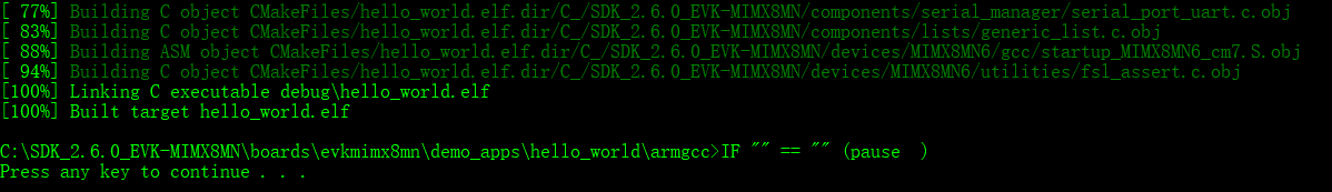
Create image using KSDK XIP example#
Users can create an unsigned bootable image by building a KSDK XIP project and convert the output to a binary file. The binary file needs to be renamed to the boot_image.bin and copied to the same folder as ucl2.xml. Then users can update the cfg.ini file to enable an option of manufacturing flow which is described in previous section.
Create image using the elftosb utility#
To create a bootable image for a specific memory, users need to know the memory map of i.MX RT106x SoC. Details of generating bootable image can be found in Chapter 4. Here are the steps to create an i.MX RT bootable image for FlexSPI NOR using elftosb utility.
Create the BD file for boot image generation. The BD file content is showed below. It is also available in the release package in “<sdk_package>/middleware/mcu-boot/bin/Tools/bd_file/imxrt10xx” folder
options {
    flags = 0x00;
    startAddress = 0x600000000x30000000;
    ivtOffset = 0x1000;
    initialLoadSize = 0x2000;
}
entryPointAddress = 0x30002000;
sources {
    elfFile = extern(0);
}
section (0)
{
}
Create the i.MX RT bootable image using elftosb utility.
Here is the example command:
Example command to generate FlexSPI NOR boot image

Example command to generate FlexSPI NOR boot image


|
ivt_flexspi_nor_xip.bin
ivt_flexspi_nor_xip_nopadding.bin
The ivt_flexspi_nor_xip_nopadding.bin will be used to generate SB file for QSPI FLASH programming in subsequent section.
Create SB file for QSPI FLASH programming#
Here is an example to create an SB file for QSPI FLASH programming for RT1060RT1064RT1170-EVK board. The details for generating SB file for bootable image programming is available in Chapter 5.
# The source block assign file name to identifiers
sources {
 myBinFile = extern (0);
}
constants {
    kAbsAddr_Start= 0x6730000000;
    kAbsAddr_Ivt = 0x6730001000;
    kAbsAddr_App = 0x6730002000;
}
# The section block specifies the sequence of boot commands to
# be written to the SB file
section (0) {
    #1. Prepare Flash option
    # 0xc0000007 is the tag for Serial NOR parameter selection
    # bit [31:28] Tag fixed to 0x0C
    # bit [27:24] Option size fixed to 0
    # bit [23:20] Flash type option
    #             0 - QuadSPI SDR NOR
    #             1 - QUadSPI DDR NOR
    # bit [19:16] Query pads (Pads used for query Flash Parameters)
    #             0 - 1
    # bit [15:12] CMD pads (Pads used for query Flash Parameters)
    #             0 - 1
    # bit [11: 08] Quad Mode Entry Setting
    #             0 - Not Configured, apply to devices:
    #                 - With Quad Mode enabled by default or
    #                 - Compliant with JESD216A/B or later revision
    #             1 - Set bit 6 in Status Register 1
    #             2 - Set bit 1 in Status Register 2
    #             3 - Set bit 7 in Status Register 2
    #             4 - Set bit 1 in Status Register 2 by 0x31 command
    # bit [07: 04]  Misc. control field
    #             3 - Data Order swapped, used for Macronix OctaFLASH devcies only
    #             (except MX25UM51345G)
    #             4 - Second QSPI NOR Pinmux
    # bit [03: 00] Flash Frequency, device specific
    load 0xc00000070xc0000107 > 0x2000;
    # Configure QSPI NOR FLASH using option a address 0x2000
    enable flexspinor 0x2000;
    #2 Erase flash as needed.
    #(Here only 64KBytes are erased, need to be adjusted to the actual
    #size of users' application)
    erase 0x670000000..0x670010000;
    #3. Program config block
    # 0xf000000f is the tag to notify Flashloader to program
    # FlexSPI NOR config block to the start of device
    load 0xf000000f > 0x3000;
    # Notify Flashloader to response the option at address 0x3000
    enable flexspinor 0x3000;
    #4. Program image
    load myBinFile > kAbsAddr_Ivt;
}
After the BD file is ready, the next step is to generate the boot_image.sb file that is for MfgTool to use later. Here is the example command:
Example command to generate SB file for FlexSPI NOR programming
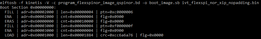
Example command to generate SB file for FlexSPI NOR programming

Example command to generate SB file for FlexSPI NOR programming
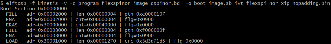
After using the above command, the boot_image.sb is generated in the elftosb utility folder.
Program Unsigned Image to Flash using MfgTool#
Use the following steps to program a boot image into a flash device
Copy the boot_image.sb file to “<mfgtool_root_dir>/Profiles/MXRT106XMRT117x/OS Firmware” folder.
Change the “name” under “[List]” to selected option in cfg.ini file in <mfgtool_root_dir> folder, for example, “name = MXRT106x-DevBootSerialFlashXiP**name = MXRT117x-DevBootFlexSpi1_FlashXiP”.
Put the RT1060RT1064RT1170-EVK board to Serial Downloader mode by setting SW7SW1 to “1-OFF, 2-OFF, 3-OFF, 4-ON”.
Power up RT1060RT1064RT1170-EVK board and insert USB cable to J9J20.
Open MfgTool, it will show as the detected device like the one shown in Figure 1.
Click “Start”, MfgTool will do manufacturing process. After completion, it will show the status as success as shown in Figure 16. Click “Stop” and close the MfgTool.
Put the RT1060RT1064RT1170-EVK board to internal boot mode and select QSPI FLASH as boot device by setting SW7SW1 to “1-OFF, 2-OFF,3-ON, 4-OFF”. Then reset the device to start running the application
Manufacturing process in Production phase#
In production phase, the image requires to be signed and possibly encrypted. In this case, the device must be configured to HAB closed mode.
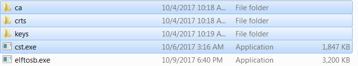
Assuming the PKI tree is ready for cst use, copy “ca”, “crts”, and “keys” folder and cst executable to the folder that holds the elftosb utility executable, as shown below
Copy required key and certificates for signed image generation
Generate signed i.MX RT bootable image#
To generate a bootable image for a specific memory, users need the memory map of the i.MX RT device SoC. Chapter 4, Generate i.MX RT bootable image, provides details for generating a bootable image. Here are the steps to generate signed i.MX RT bootable image using the elftosb utility.
Generate the BD file for boot image generation. The BD file content is showed in the figure below. It is also available in the release package in “<sdk_package>/middleware/mcu-boot/bin/Tools/bd_file/imxrt10xx”<install_dir>/Tools/bd_file/imxrt10xx” folder.
options {
    flags = 0x08;
    startAddress = 0x670000000;
    ivtOffset = 0x1000;
    initialLoadSize = 0x2000;
    //DCDFilePath = "dcd.bin";
    # Note: This is required if the cst and elftsb are not in the same folder
    //cstFolderPath = "path/CSTFolder";
    # Note: This is required if the default entrypoint is not the Reset_Handler
    # Please set the entryPointAddress to base address of Vector table
    //entryPointAddress = 0x670002000;
}
sources {
    elfFile = extern(0);
}
constants {
    SEC_CSF_HEADER = 20;
    SEC_CSF_INSTALL_SRK = 21;
    SEC_CSF_INSTALL_CSFK = 22;
    SEC_CSF_INSTALL_NOCAK = 23;
    SEC_CSF_AUTHENTICATE_CSF = 24;
    SEC_CSF_INSTALL_KEY = 25;
    SEC_CSF_AUTHENTICATE_DATA = 26;
    SEC_CSF_INSTALL_SECRET_KEY = 27;
    SEC_CSF_DECRYPT_DATA = 28;
    SEC_NOP = 29;
    SEC_SET_MID = 30;
    SEC_SET_ENGINE = 31;
    SEC_INIT = 32;
    SEC_UNLOCK = 33;
}
section (SEC_CSF_HEADER;
    Header_Version="4.2",
    Header_HashAlgorithm="sha256",
    Header_Engine="DCP",
    Header_EngineConfiguration=0,
    Header_CertificateFormat="x509",
    Header_SignatureFormat="CMS")
{
}
section (SEC_CSF_INSTALL_SRK;
    InstallSRK_Table="keys/SRK_1_2_3_4_table.bin", // "valid file path"
    InstallSRK_SourceIndex=0)
{
}
section (SEC_CSF_INSTALL_CSFK;
    InstallCSFK_File="crts/CSF1_1_sha256_2048_65537_v3_usr_crt.pem", // "valid file path"
    InstallCSFK_CertificateFormat="x509") // "x509"
{
}
section (SEC_CSF_AUTHENTICATE_CSF)
{
}
section (SEC_CSF_INSTALL_KEY;
    InstallKey_File="crts/IMG1_1_sha256_2048_65537_v3_usr_crt.pem",
    InstallKey_VerificationIndex=0, // Accepts integer or string
    InstallKey_TargetIndex=2) // Accepts integer or string
{
}
section (SEC_CSF_AUTHENTICATE_DATA;
    AuthenticateData_VerificationIndex=2,
    AuthenticateData_Engine="DCP",
    AuthenticateData_EngineConfiguration=0)
{
}
section (SEC_SET_ENGINE;
    SetEngine_HashAlgorithm = "sha256", // "sha1", "Sha256", "sha512"
    SetEngine_Engine = "DCP", // "ANY", "SAHARA", "RTIC", "DCP", "CAAM" and "SW"
    SetEngine_EngineConfiguration = "0") // "valid engine configuration values"
{
}
section (SEC_UNLOCK;
    Unlock_Engine = "SNVS, OCOTP", // "SRTC", "CAAM", SNVS and OCOTP
    Unlock_features = "ZMK WRITE, SRK REVOKE")
{
}
Generate the i.MX RT bootable image using the elftosb utility file.
Here is the example command:
Example command to generate signed boot image
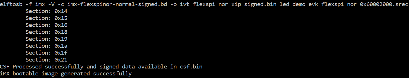
Example command to generate signed boot image
|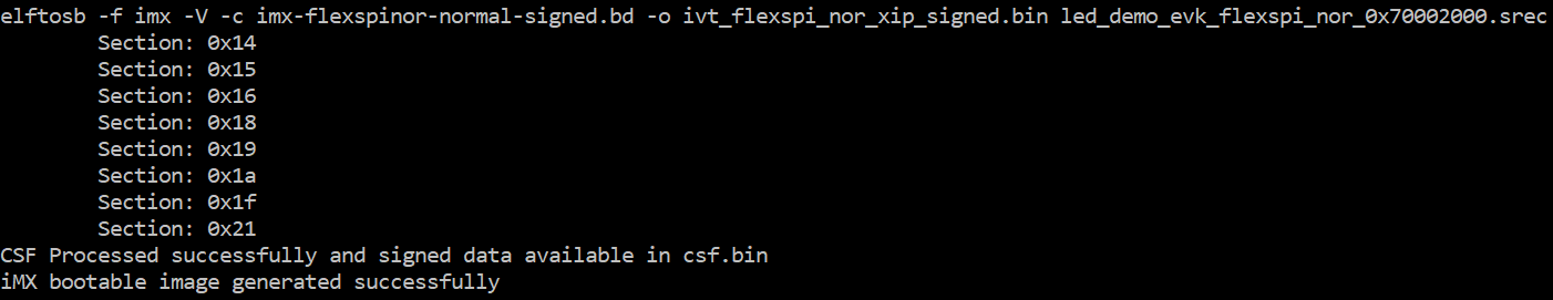
After the above command, two bootable images are generated:
ivt_flexspi_nor_xip_signed.bin
ivt_flexspi_nor_xip_signed_nopadding.bin
The ivt_flexspi_nor_xip_signed_nopadding.bin will be used to generate SB file for HyperFlashQSPI NOR Flash programming in a subsequent section.
Create SB file for Fuse programming#
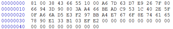
In the keys folder, there is a file named “SRK_1_2_3_4_fuse.bin”. This is the HASH table for SRK authentication during boot. It must be programmed to fuses to enable secure boot mode.
Below is an example file
Example SRK_1_2_3_4_fuse.bin file

Below is an example BD file which shows the procedure to program fuses. The fuse field is a 32-bit long word data. It will be programmed into the fuses by Flashloader in little-endian mode.
# The source block assign file name to identifiers
sources {
}
constants {
}
# The section block specifies the sequence of boot commands to be written to the SB file
# Note: this is just a template, please update it to actual values in users' project
section (0) {
    # Program SRK table
    load fuse 0xD132E7F1 > 0x18;
    load fuse 0x63CD795E > 0x19;
    load fuse 0x8FF38102 > 0x1A;
    load fuse 0x22A78E77 > 0x1B;
    load fuse 0x01019c82 > 0x1C;
    load fuse 0xFC3AC699 > 0x1D;
    load fuse 0xF2C327A3 > 0x1E;
    load fuse 0xDAC9214E > 0x1F;
    # Program SEC_CONFIG to enable HAB closed mode
    load fuse 0x00000002 > 0x06;
}
The last command in above BD file is used to enable HAB closed mode by setting SEC_CONFIG [1] bit in the fuse to 1.
After BD file is ready, the next step is to create SB file for Fuse programming to enable HAB closed mode.
An example command is shown below:
Example command to generate SB file for Fuse programming
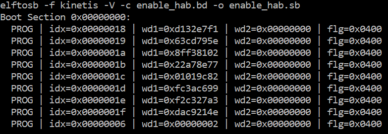
After the command “enable_hab.bd -o enable_hab.sb” in the figure above is executed, a file named “enable_hab.sb” gets generated. It is required in MfgTool for Secure Boot solution.
Create SB file for Image encryption and programming for HyperQSPI Flash#
Following chapter 5, here is an example to generate the SB file for image encryption and programming on HyperQSPIFlash for MIMXRT10506064151020-EVK board.
Refer to the BD file in Section 5.1.3, Generate SB file for FlexSPI NOR Image encryption and programming.
After the BD file is ready, the next step is to generate the SB file. Refer below for an example command.
Example command to generate SB file for FlexSPI NOR image encryption and programming
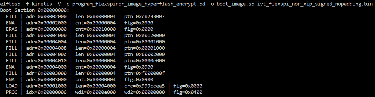
Example command to generate SB file for FlexSPI NOR image encryption and programming
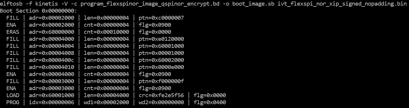
Example command to generate SB file for FlexSPI NOR image encryption and programming
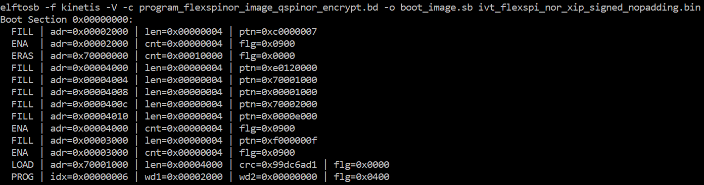
After the command “program_flexspinor_image_hyperflash_qspinor_encrypt.bd -o boot_image.sb ivt_flexspi_nor_xip_signed_nopadding.bin” in the figure above , a file named “boot_image.sb” is generated in the folder that contains the elftosb utility executable.
Create signed Flashloader image#
The BD file for signed Flashloader image generation is similar as the one in Section 7.1.2.1 Generate signed i.MX RT bootable image.
The only difference is that the startAddress is 0x20000000 and IVTOffset is 0x400.
After the BD file is ready, the next step is to generate i.MX boot image using the elftosb utility. The example command is as below:
Example command for Signed Flashloader image generation
After the command “imx-dtcm-signed.bd -o ivt_flashloader_signed.bin flashloader.srec” in the figure above, two bootable images are generated:
ivt_flashloader_signed.bin
ivt_flashloader_signed_nopadding.bin
The first one is required by MfgTool for Secure Boot.
Program Signed Image to Flash using MfgTool#
Here are the steps to program boot image into the Flash device
Copy the boot_image.sb file, ivt_flashloader_signed.bin and enable_hab.sb to “<mfgtool_root_dir>/Profiles/MXRT106X/OS Firmware” folder
Change the “name” under “[List]” to “MXRT106x-SecureBoot” in cfg.ini file in <mfgtool_root_dir> folder
Put the RT10604-EVK board to Serial Downloader mode by setting SW7 to “1-OFF, 2-OFF, 3-OFF, 4-ON”
Power up RT10604-EVK board, and insert USB cable to J9
Open MfgTool, it will show the detected device.
Click “Start”, MfgTool will do manufacturing process and after completion, it will show the status as success. Click “Stop” and close the MfgTool
Put the RT10604-EVK board to internal boot mode and select QSPI FLASH as boot device by setting SW7 to “1-OFF, 2-OFF,3-ON, 4-OFF”. Reset the device. The LED above the ethernet interface starts blinking which indicates that the image is running.
Generate KeyBlob manually#
Users may need to generate the KeyBlob manually in some cases. The Flashloader supports such usage with blhost.
The KeyBlob must be generated when the device works under HAB closed mode with signed Flashloader application.
Assuming the dek.bin is ready (generated by the elftosb utility during encrypted image generation). Here is an example command to generate KeyBlob block.
Generate KeyBlob using the Flashloader
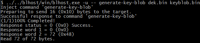
After the command, “blhost.exe -u –generate-key-blob dek.bin keyblob.bin” in figure above is executed, a “keyblob.bin” file gets generated.
Example KeyBlob
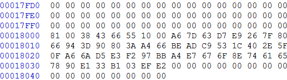
With the encrypted image generated by the elftosb utility and keyblob.bin generated by the Flashloader, it is also feasible to combine the encrypted image and keyblob.bin. Then create a complete encrypted boot image with a Hex Editor. In this example, the KeyBlob offset is 0x18000 in the boot image.
The figure below is an example piece of encrypted image combined by Hex Editor.
Create complete encrypted image using Hex editor